ENG | Arduino, Weather or Environmental Sensors
A guide on using environmental sensors like HTU21D, BMP280, BMP388, and DS18B20 with Arduino boards for monitoring temperature, humidity, and pressure. Includes wiring instructions, code examples, and project ideas for weather stations and data logging.
Introduction
Environmental sensors are crucial components in many Arduino projects aimed at monitoring and gathering data about surrounding conditions. This guide focuses on these specific sensors:
- HTU21D for measuring temperature and humidity
BME280BMP280 for measuring pressure, temperature,and humidity- BMP388 for pressure and temperature
- DS18B20 for temperature (with gnuplot example) By integrating these sensors with an Arduino board, you can create powerful environmental monitoring systems, weather stations, or indoor air quality assessments.
Connecting I²C Sensors
The I²C (Inter-Integrated Circuit) protocol is a popular communication standard that allows multiple devices to be connected using just two signal wires (SDA and SCL).
Wiring the BME280 to an Arduino is straightforward:
- VCC (VIN) to 3.3V (sometimes 5V)
- GND to GND
- SCL to A5 (or SCL pin)
- SDA to A4 (or SDA pin)
This simplifies wiring and makes it easier to integrate several sensors on the same Arduino board. Most Arduino boards have I2C support built-in, but you may need to enable it explicitly in some cases by calling Wire.begin() in your setup().
It’s good to find pinout, cause depending on Arduino version and clone, some pins may not have descripion. Sensors are usually powered by 3.3V and all we need is to connect 3.3V, GND, SDA-A4, SCL-A5 using four wires and multiple devices can be connected.
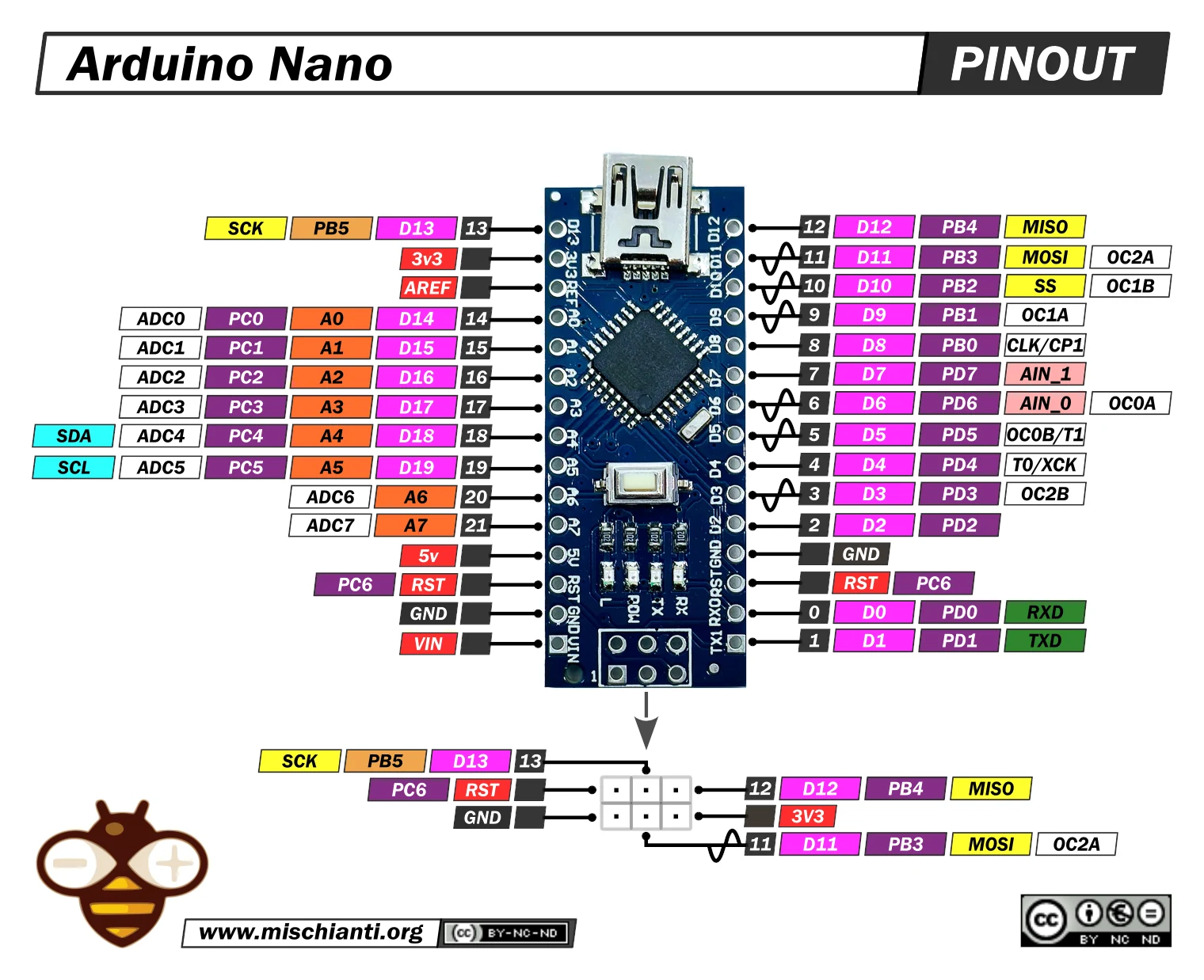 Arduino Nano Pinout, image from https://mischianti.org
Wiki article about I²C
I²C Scanner Utility
If I²C address is not clearly specified. There is I2C Scan utility in Examples->Wire->i2c_scanner. When executed it writes something like this:
1
2
3
4
5
I2C Scanner
Scanning...
I2C device found at adress 0x40  !
I2C device found at adress 0x76  !
done
(I had HTU21D and BMP280 connected at the same time)
Some I2C addresses
| Address | Device | |
|---|---|---|
| 0x3C | 60 | SSD1306 OLED Display driver |
| 0x40 | 64 | HTU21D Temperature and Relative Humidity sensor |
| 0x44 | 68 | Sensirion SHT40 Temperature and humidity sensor |
| 0x51 | 81 | RTC: PCF8563 |
| 0x57 | 87 | EEPROM on DS3231 RTC module |
| 0x62 | 98 | Sensirion SCD41 CO2, temperature and humidity sensor |
| 0x68 | 104 | RTC: DS3231, DS1307, PCF8523 |
| 0x76 | 118 | Bosch BMP180 Temperature and Pressure sensor |
| 0x76 | 118 | Bosch BME280 Temperature, Humidity and Pressure sensor |
| 0x77 | 119 | Bosch BMP388 Temperature and Pressure sensor |
NOTE: Technically default for BMP388 is 0x76 as well, but it’s programmable and maybe board has different address to differentiate them.
Lowest bit of address differentiates between read and write operation. Arduino and MicroPython use highest 7bits of address. So don’t be surprised if you see 0x3c in I2C scan and 0x78 in the datasheet.
HTU21D Temperature and Relative Humidity I2C sensor
The HTU21D is a compact and low-power sensor capable of measuring both temperature and relative humidity. Its I²C interface makes it simple to integrate with an Arduino board using just four wires (3.3V, GND, SDA, SCL).
This code demonstrates how to read temperature and humidity values from the HTU21D sensor using the I²C protocol. The readValue() function handles the low-level communication, while readTemp() and readHum() calculate the actual temperature and humidity values based on the raw sensor data.
1
2
3
4
5
6
7
8
9
10
11
12
13
14
15
16
17
18
19
20
21
22
23
24
25
26
27
28
29
30
31
32
33
34
35
36
37
38
39
40
41
42
43
44
45
46
47
48
49
50
51
52
53
54
55
56
57
58
59
60
61
62
63
64
65
66
67
68
69
70
71
72
73
74
75
76
77
78
79
80
81
82
83
84
85
86
87
88
89
90
91
92
93
94
95
96
97
98
99
/////////////////////////////////////////////////////////////////////////////
// Includes
#include <Wire.h>

/////////////////////////////////////////////////////////////////////////////
// HTU21D temperature / humidity
// Original from sparkfun library 2016
// Rewritten in March 2024, Pavel Perina

class htu21d {
private:
  // Unshifted 7-bit I2C address for the sensor
  static constexpr uint8_t HTDU21D_ADDRESS = 0x40;

  static constexpr uint8_t TRIGGER_TEMP_MEASURE_HOLD   = 0xE3;
  static constexpr uint8_t TRIGGER_HUMD_MEASURE_HOLD   = 0xE5;
  static constexpr uint8_t TRIGGER_TEMP_MEASURE_NOHOLD = 0xF3;
  static constexpr uint8_t TRIGGER_HUMD_MEASURE_NOHOLD = 0xF5;
  static constexpr uint8_t WRITE_USER_REG              = 0xE6;
  static constexpr uint8_t READ_USER_REG               = 0xE7;
  static constexpr uint8_t SOFT_RESET                  = 0xFE;

  static uint16_t readValue(uint8_t cmd)
  {
    // Request a humidity or temperature reading
    Wire.beginTransmission(HTDU21D_ADDRESS);
    Wire.write(cmd);
    Wire.endTransmission();

    // Hang out while measurement is taken. 50mS max, page 4 of datasheet.
    delay(55);

    // Comes back in three bytes, data(MSB) / data(LSB) / Checksum
    Wire.requestFrom(HTDU21D_ADDRESS, (uint8_t)3);

    // Wait for data to become available
    int counter = 0;
    while (Wire.available() < 3) {
      counter++;
      delay(5);
      if (counter > 20)
        return INVALID_VALUE;
    }

    const uint8_t msb = Wire.read();
    const uint8_t lsb = Wire.read();
    const uint8_t checksum = Wire.read();
    uint16_t rawValue = ((unsigned int)msb << 8) | (unsigned int)lsb;
    rawValue &= 0xFFFC; // Zero out the status bits
    return rawValue;
  }

public:
  static constexpr float INVALID_VALUE = -100.0f;

  static float readHum()
  {
    // Measure humidity with no bus holding
    uint16_t rawValue = readValue(TRIGGER_HUMD_MEASURE_NOHOLD);
    // Given the raw humidity data, calculate the actual relative humidity
    float hum = rawValue / (float)65536;      // 2^16 = 65536
    hum = -6.0f + (125.0f * hum);             // From page 14
    return hum;
  }

  static float readTemp()
  {
    // Request the temperature
    uint16_t rawValue = readValue(TRIGGER_TEMP_MEASURE_NOHOLD);

    // Given the raw temperature data, calculate the actual temperature
    float temp = rawValue / (float)65536;     // 2^16 = 65536
    temp = (float)(-46.85 + (175.72 * temp)); // From page 14
    return temp;
  }
}; // class htu21d


void setup()
{
  // put your setup code here, to run once:
  Serial.begin(9600);
  while (!Serial)
    ;
  Wire.begin();
}


void loop()
{
  // put your main code here, to run repeatedly:
  const float htuTemp = htu21d::readTemp();
  const float htuHum  = htu21d::readHum();
  Serial.print(htuTemp);
  Serial.print(",");
  Serial.print(htuHum);
  Serial.println("");
  delay(500);
}
Example output:
1
2
3
4
5
6
22.11,37.28
22.10,37.27
22.10,37.27
22.11,37.26
22.11,37.24
22.12,37.24
DS18B20 1-Wire Temperature sensor
Schema
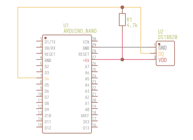 Arduino Nano and DS18B20
Installing libraries
Install Arduino libraries including dependencies
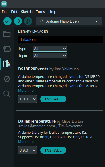 This picture shows where to install libraries from online repository.
1
2
3
4
5
6
7
8
9
10
11
12
13
14
15
16
17
18
19
20
21
22
23
24
25
26
27
28
29
30
31
32
33
34
35
36
// DS18B20 1-Wire digital temperature sensor with Arduino example code.

// Include the required Arduino libraries
#include <OneWire.h>
#include <DallasTemperature.h>

// Define to which pin of the Arduino the 1-Wire bus is connected
constexpr int oneWirePin = 4;

// Create a new instance of the oneWire class to communicate with any OneWire device:
OneWire oneWire(oneWirePin);

// Pass the oneWire reference to DallasTemperature library
DallasTemperature sensors(&oneWire);


void setup(void)
{
  // Begin serial communication at a baud rate of 9600
  Serial.begin(9600);
  // Initialize the library
  sensors.begin();
}


void loop(void)
{
  // Send the command for all devices on the bus to perform a temperature conversion
  sensors.requestTemperatures();
  // Fetch the temperature in degrees Celsius for device index (zero for 1st device)
  const float tempC = sensors.getTempCByIndex(0);
  // Print the temperature in Celsius in the Serial Monitor
  Serial.println(tempC);
  // Wait 1 second:
  delay(1000);
}
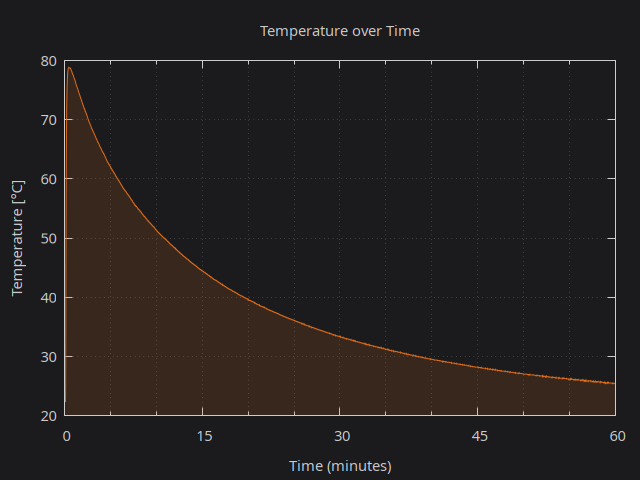
Side Note: Plotting Data (on Linux)
Now let’s have some fun.
- Prepare boiling water
- Exit Arduino IDE
- Put sensor into coffee mug
- On the console type these command. First one reads serial port, second one reads input and writes it into console and file at the same time.
1
cat /dev/ttyUSB0 | tee coffee &
- Pour in the hot water and watch temperature. Example output (shortened)
1
2
3
4
5
6
7
8
22.37
25.94
57.19
70.56
75.44
77.44
77.87
78.19
- Keep it for few tens of minutes, while resisting to drink it 😀 Then press Ctrl+C to stop logging.
1
2
3
4
fg23.81
[1]  + running    cat /dev/ttyUSB0 | tee coffee
23.81
^C
- Write some script to plot data, e.g.
1 2 3 4 5 6 7 8 9 10 11 12 13 14 15 16 17 18
# Pavel Perina, 2024-03-13 set terminal pngcairo size 640,480 enhanced font "Noto Sans,11,Normal" background "#1b1b1e" set output 'arduino_plot_coffee_temp_dark.png' set border linecolor rgb "#cccccc" set title tc rgb "#cccccc" 'Temperature over Time' set xlabel tc rgb "#cccccc" 'Time (minutes)' set ylabel tc rgb "#cccccc" 'Temperature [°C]' set xr [0:*] # Adjusts x-range based on data, * means it will automatically find the max set yr [20:80] # Your specified y-range set xtics 15 textcolor rgb "#cccccc" # Major x-ticks every 15 minutes set mxtics 3 # Adds minor x-tics between major ones, adjust as needed set grid xtics mxtics ytics linecolor rgb "#cccccc" # Enable grid for easier reading set nokey set style fill transparent solid 0.15 # Convert x-values from seconds to minutes for plotting plot 'coffee' using ($0/60.0):1 with filledcurves x1 lc rgb "#de6b18", \ 'coffee' using ($0/60.0):1 with lines lc rgb "#de6b18" - Enjoy the result
BME280 and BMP280 Pressure, Temperature(, and Huminidy) Sensor
Difference between BMP280 and BME280 sensors is that BMP280 sensor can’t read humidity.
There is one detailed article about this sensor How To Use BME280 Pressure Sensor With Arduino and SparkFun BME280 Arduino Library
I tried to write some simple code for using sensor without 3rd party library to read data. It was not so simple, because it’s hard to find reference when something does not work. Are readings ok? Are calibration data ok? Are bit operations ok? How to even debug code on Arduino other way than creating debug outputs to terminal? In the end I succeeded.
Some minimal example is on my GitHub: https://github.com/pavel-perina/arduino-bmp280-minimal
By the formula to get sea level pressure is on wiki:
1
2
3
4
5
6
7
8
9
10
11
12
13
14
15
16
17
18

## BMP388, BMP390 Pressure and Temperature Sensor

From [AdaFruit site](https://learn.adafruit.com/adafruit-bmp388-bmp390-bmp3xx/pinouts):

Pinout

| Pin | Description |
|----:|-------------|
| VIN | Input Voltage 3-5V |
| 3Vo | 3.3V from stabilizer (MIC5219, MIC5225, ...) |
| GND | Ground |
| SCK, SCL | Clock for both I2C and SPI |
| SDO | Serial Data Out (MISO) |
| SDI, SDA | Serial Data In (MOSI), I2C Serial Data |
| CS | SPI Chip Select, 3-5V |
| INT | Interrupt (measurement ready) |
MOSI = Master Out -> Slave In Microcontroler Out -> Sensor In MISO = Master In <- Slave Out Microcontroler In <- Sensor Out ```
Board uses voltage regulator (MIC5219-3.3YM5-TR), level shifter (2N7002PS on SDI&SCK, diode on CS) and sensor.
When logic levels of Microcontroler is 5V, VIN should be 5V too.
Connection to Arduino via I2C:
| Sensor | Arduino | |
|---|---|---|
| VIN | 5V | |
| GND | GND | |
| SCK | A5 | |
| SDI | A4 |
Some minimal example is on my GitHub: https://github.com/pavel-perina/arduino-bmp280-minimal
Other resources
Side Note
- Images were created using EasyEDA, Affinity Designer 2
Changelog
- 2025-09-25: Added decimal addresses and SCD41 sensor