ENG | Arduino Pro Mini & RTC: Power consumption experiments
Motivation
I decided to explore power consumption of Arduino Pro Mini and use sleep mode to get power consumption as low as possible so data logger can be powered from battery. I had some notes from 2016, but here I focused solely on SD card (which was lot “fun”) and other notes are somewhat chaotic and incomplete.
Modifications
Arduino Pro Mini and ZS-042 module with DS3231 RTC, both from 2016 were used.
- Arduino Pro Mini had power LED disabled by cutting trace on circuit board with knife
- ZS-042 had LED and charging circuit disabled by removing resistors (later SQW/INT pullup trace cut)
Arduino Pro Mini and USB-Serial Converter
Making this shit work took me a few hours. What can go wrong? EVERYTHING!
Step 1: Try to find out what Arduino Pro Mini do you have.
Could be 5V 16MHz or 3.3V 8MHz. Atmega328 or Atmega168 - this is at least clearly written by dark gray color on black chip. Distinction between 5V a 3.3V versions are voltage regulator and oscilator, because Arduino is not safe to operate at 16MHz with lower voltage.
Stack exchange thread about identification
Step 2: Try using fake USB-Serial convertor
Get USB to serial with with PL2303 chip which is labeled as 3.3V. Realize that chip is fake, recognized as fake by driver and won’t work on Windows. (This was hopefully in my 2016 notes, you can make it work, but it’s not worth it. At least it was possible to replace driver by unsigned, hacked one 8 years ago.)
Solution: Buy another USB-Serial convertor
Step 3: Guesstimate proper wiring
- Connect VCC and GND. Should VCC be connected to RAW or 3V3? Does it matter? Well, if USB-Serial has 3.3V output, it’s possible to bypass it.
- Connect TX (transmit) to RXI (receive input) of Arduino and connect RX (receive)
- At this point it may randomly work - randomly if you fiddle with wires and accidentaly reset Arduino or try pressing reset randomly
- Desperately try to disconnect everything, disconnect and reconnect USB cable, different set of wires
- Note that RX/TX pins on USB-Serial are not blinking. Try to short RX/TX to create loopback to check if convertor works and try it with CoolTerm or something. It works. What?
- Look at different USB to Serial converters, some have RST pin! Why? Hmmm….
- Find Arduino Pro Mini Schematics - there is DTR which is nowhere on Arduino. Try finding random pinouts until you find one when your GRN pin is labeled DTR.
- Since now upload works. But nothing on I2C bus.
| USB-Serial | Arduino Pro Mini | Note, color |
|---|---|---|
| GND | GND | Black |
| CTS | BLK(GND) | Could be disconnected Clear to send, Brown |
| VCC | VCC | Red |
| TX | RXI | Orange |
| RX | TXO | Yellow |
| DTR | GRN or DTR | GRN means green wire of (un)certain FTDI converter Data terminal ready, Green |
BLK and GND are connected together
Step 4: Analyze I2C issues
There’s power off switch on USB-Serial convertor. I already noticed that when the power is off, LED on Arduino stops blinking (there was blink program), but LED on convertor shines, although with lower intensity. Later I noticed that even when VCC is disconnected, some devices are somehow powered trough data pins (what else) and ground.
So it’s best … actually necessary … to disconnect everything from USB when wiring is changed and also it means that all power measurements have to be done with serial communication disconnected so current has only one path. Otherwise I2C devices can be stuck and not responding.
Also double check which pin is A4/A5 and which is SCL/SDA. Just saying …
At this point it’s clear that we can’t output anything to serial during power measurement and LED and timing must be used.
Power measurements
Wiring
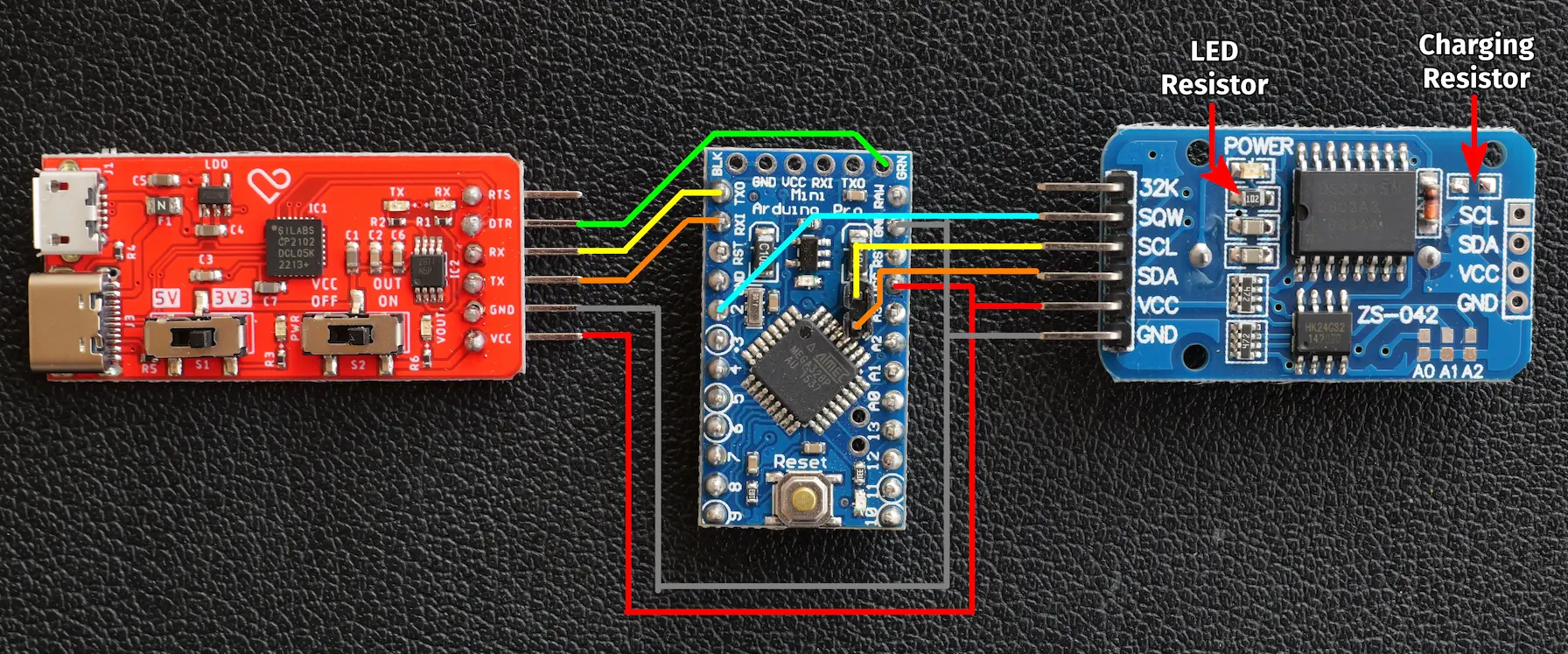 Arduino Pro Mini, CP1202 universal USB Serial converter and ZS-042 RTC Module
Note: these are not exact pieces that were used for power measurements. LEDs on both RTC and Arduino are present here.
Code
Full source is here for download: logger-20240330.7z
1
2
3
4
5
6
7
8
9
10
11
12
13
14
15
16
17
18
19
20
21
22
23
24
25
26
27
28
29
30
31
32
33
34
35
36
37
38
39
40
41
42
43
44
45
46
47
48
49
50
51
52
53
54
55
56
57
58
59
60
61
62
63
64
65
66
67
68
69
70
71
72
73
74
75
76
77
78
79
80
81
82
83
84
85
86
87
88
89
90
91
92
93
94
95
96
97
98
99
100
101
102
103
104
105
106
107
108
109
110
111
112
113
114
115
116
117
118
119
120
121
122
123
124
125
126
127
128
129
130
131
132
133
134
135
136
137
138
139
140
141
142
143
144
145
146
147
148
149
150
151
152
153
154
155
156
157
158
159
160
161
162
163
164
165
166
167
168
169
170
171
172
173
174
175
176
177
178
179
180
181
182
183
//! \file   logger-20240330.ino
//! \brief  Datalogger v2: power consumption optimization
//! \date   2024-03-30
//! \author Pavel Perina

#include "rtc_ds3231.h"
#include <Wire.h>
#include <avr/sleep.h>

constexpr uint8_t RTC_INT_PIN = 2;  // must be 2,3, input pin on Arduino
constexpr uint8_t RTC_INT = RTC_INT_PIN - 2;
volatile bool g_intTriggered = false;

#define TEST_RUN 1

static uint8_t bcdToBin (uint8_t val)
{
  return val - 6 * (val >> 4);
}


static uint8_t binToBcd (uint8_t val)
{
  return val + 6 * (val / 10);
}


void setupInterrupt()
{
  pinMode(RTC_INT_PIN, INPUT_PULLUP);
  attachInterrupt(
    RTC_INT,
    []() {
      // no delay or serial communication allowed here
      // actually this code is quite irrelevant
      g_intTriggered = true;
    },
    FALLING
  );
}


void dot()
{
  digitalWrite(LED_BUILTIN, HIGH);
  delay(150);
  digitalWrite(LED_BUILTIN, LOW);
  delay(150);
}


void dash()
{
  digitalWrite(LED_BUILTIN, HIGH);
  delay(450);
  digitalWrite(LED_BUILTIN, LOW);
  delay(150);
}


void enterSleep(bool adcDisable = true)
{
  // Wait for serial writes to complete
  Serial.flush();
  delay(100);

  dot(); dot(); dot(); // S (...) for sleep

  uint8_t keep_ADCSRA = ADCSRA;
  if (adcDisable) {
    ADCSRA = 0;
  }

  // Enter sleep mode
  set_sleep_mode(SLEEP_MODE_PWR_DOWN);
  sleep_enable();
  sleep_cpu();

  // ...zzzZZZzzz...

  //  Wake up code (after interrupt from RTC)
  sleep_disable();

  // Restore ADC
  ADCSRA = keep_ADCSRA;

  dot(); dash(); // A (.-) for awake, alarm
}


void printTimeAndSetupAlarm(Rtc3231 &rtc)
{
  Serial.print("Time is: ") ;
  uint8_t rawDateTime[Rtc3231::RTC_TIME_DATA_LEN];
  char formattedDateTime[Rtc3231::DECODED_TIME_LEN];
  rtc.readTimeData(rawDateTime);
  rtc.formatTimeData(formattedDateTime, rawDateTime);
  Serial.println(formattedDateTime);

#if !TEST_RUN
  Serial.print("Setting up alarm in one minute (");
  uint8_t alarmData[4] = {
    rawDateTime[0], // copy seconds in BCD from current time
    binToBcd( (bcdToBin(rawDateTime[1]) + 1) % 60),
    0x80, // invalid hour => when minutes&seconds match
    0x80  // invalid day  => when minutes&seconds match
  };
#else
  Serial.print("Setting up alarm in 20 seconds (");
  uint8_t alarmData[4] = {
    binToBcd( (bcdToBin(rawDateTime[0]) + 20) % 60),
    0x80, // invalid minute => seconds must match
    0x80, // invalid hour   => seconds must match
    0x80  // invalid day    => seconds must match
  };
#endif

  Serial.print(alarmData[1], HEX);
  Serial.print(":");
  Serial.print(alarmData[0], HEX);
  Serial.println(")");
  rtc.busWrite(Rtc3231::ADDR_A1, alarmData, 4);

  // control & status registers
  uint8_t data[2] = {
    // set interrupt mode & alarm1 enable
    Rtc3231::CONTROL_INTCN | Rtc3231::CONTROL_A1E,
    // clear active alarms and errors, also disable 32kHz signal (STATUS_EN32K=0)
    0
  };
  rtc.busWrite(Rtc3231::ADDR_CONTROL, data, 2);
}


void setup()
{
  pinMode(LED_BUILTIN, OUTPUT);
  Wire.begin();
  Serial.begin(9600);
  while (!Serial)
    ;

  Rtc3231 rtc;
  dot(); dot(); // I (..) for init

  Serial.println("Disabling alarm ...");

  // TODO we can enable SQW and disable SQW here
  rtc.disableAndClearAlarm();

  printTimeAndSetupAlarm(rtc);

  setupInterrupt();

  Serial.println("Preparing to sleep in 5s ...");
  delay(5000);
  Serial.println("Good night ...");
  enterSleep(false);
}


void loop()
{
  static uint8_t s_pass = 0;
  if (g_intTriggered) {
    Rtc3231 rtc;
    delay(1000);
    dash(); dash(); dash(); // O (---) okay
    g_intTriggered = false;
    s_pass++;
    Serial.print("Interrupted by alarm, pass counter = ");
    Serial.println(s_pass);
    printTimeAndSetupAlarm(rtc);
    Serial.println("Preparing to sleep in 5s ...");
    delay(5000);
    Serial.println("Entering sleep");
    enterSleep();
  } else {
    Serial.println("ERROR: int not triggered");
    dot(); // E (.) for error
  }
}
Sample output
1
2
3
4
5
6
7
8
9
10
11
12
13
14
15
Disabling alarm ...
Time is: 2024-03-30T20:11:36Z
Setting up alarm in 20 seconds (80:56)
Preparing to sleep in 5s ...
Good night ...
Interrupted by alarm, pass counter = 1
Time is: 2024-03-30T20:11:59Z
Setting up alarm in 20 seconds (80:19)
Preparing to sleep in 5s ...
Entering sleep
Interrupted by alarm, pass counter = 2
Time is: 2024-03-30T20:12:22Z
Setting up alarm in 20 seconds (80:42)
Preparing to sleep in 5s ...
Entering sleep
Breakdown of code
Basically we need the following:
- Setup interrupt (Pin D2=INT0 on falling edge)
1
2
3
4
5
6
7
8
constexpr uint8_t RTC_INT_PIN = 2;        // must be 2,3, input pin on Arduino
volatile  bool    g_intTriggered = false; // actually not necessary, we have only one way how to interrupt sleep
//⋮
void setupInterrupt()
{
  pinMode(digitalPinToInterrupt(RTC_INT_PIN), INPUT_PULLUP);
  attachInterrupt(RTC_INT, []() { g_intTriggered = true; }, FALLING ); // LOW seems to work as well
}
- Program RTC interrupt before sleep
- Get current time (at least seconds and minutes)
- Set time of the alarm (current time plus wait duration, handle overflow)
- Enable alarm in control register
- Clear/reset interrupt bits in RTC chip’s status register to acknowledge alarm
- Enter sleep:
1
2
3
4
5
6
7
8
9
#include <avr/sleep.h>
//⋮
// Enter sleep mode
set_sleep_mode(SLEEP_MODE_PWR_DOWN);
sleep_enable();
sleep_cpu();
// ...zzzZZZzzz...
//  Wake up code (after interrupt from RTC)
sleep_disable();
- Optionally turn off and on ADCs as shown in the full code
Power consumption
- Peak cca 9mA (LED flashing, …)
- Arduino&RTC during delay() 4.45mA
- Arduino&RTC during delay() 3.85mA with pins D0-D13,A0-A3,A6,A7 set to output/low (0.6mA saving when it’s on)
- Arduino&RTC during sleep_cpu(), 0.23mA
- Arduino&RTC during sleep_cpu() with ADC disabled, 0.15mA (0.08mA saving)
- Arduino&RTC during sleep_cpu() with ADC disabled and pins low, 0.14mA (measurement error?)
In theory, Arduino and RTC can be powered from power bank for years. Sadly power bank shuts down after maybe 30 seconds when load is not significant enough to be detected. But maybe we can power it by CR2032 coin cell for few weeks.
It’s possible to disable some peripherals, which I did, but it has zero effect in sleep mode and as video from Kevin Darrah (in the links below) suggest it may break things.
Upgrade attempt 1.1 (failed)
Naive solution
There is one problem though - when I measure current through RTC module ground pin, it’s roughly 90µA. Not much, but at this point it’s more than Arduino which contributed by another 50-60µA.
I tried to power RTC from Arduino’s pin 10, but somehow it does not enter sleep mode. Or to be more precise, interrupt occured just about the same time and depending on timing, Arduino either ended sleeping forever or woke instantly as it entered sleep mode (that was also dependent on whether interrupt was set to FALLING or LOW).
Datasheet says the following:
Control Register (0Eh)
Bit 6: Battery-Backed Square-Wave Enable (BBSQW). When set to logic 1 with INTCN = 0 and VCC < VPF, this bit enables the square wave. When BBSQW is logic 0,the INT/SQW pin goes high impedance when VCC < VPF. This bit is disabled (logic 0) when power is first applied.
(VPF means power failure voltage and is roughly 2.5V and it does not state what happens with INTCH=1,BBSQW=1)
At this point article Using a $1 DS3231 Real-time Clock Module with Arduino, Addendum: 2014-10-28 Pin Powering the RTC states, that with bit BBSQW enabled, interrupt works.
But according to forums, there is still problem, that RTC may be powered via SCL,SDA pins.
Upgrade attempt 1.2
Study, added 2024-04-03
After being frustrated and taking few days break I tried to read some information and came to this
This article deals with one interesting aspect of powering RTC from data pin that is generally not mentioned:
The most important mod is disconnecting the pullup resistor from the INT/SQW pin. That resistor is connected to the module’s Vcc pin, but when power is shut off, there will be no voltage there. So the pullup resistor may become a pulldown resistor, and power would be turned back on prematurely. The solution is to disconnect the pullup resistor.
This is actually encrypted in datasheet:
Active-Low Interrupt or Square-Wave Output. This open-drain pin requires an external pullup resistor connected to a supply at 5.5V or less. This multifunction pin is determined by the state of the INTCN bit in the Control Register (0Eh). When INTCN is set to logic 0, this pin outputs a square wave and its frequency is determined by RS2 and RS1 bits. When INTCN is set to logic 1, then a match between the timekeeping registers and either of the alarm registers activates the INT/SQW pin (if the alarm is enabled). Because the INTCN bit is set to logic 1 when power is first applied, the pin defaults to an interrupt output with alarms disabled. The pullup voltage can be up to 5.5V, regardless of the voltage on VCC. If not used, this pin can be left unconnected.
Yes, when we connect VCC to data pin and it’s voltage is set to zero, voltage on INT output goes to zero instead of 5V 🤦♂️.
Other posible problem may be clearing interrupt while alarm time still matches current time, but at the moment I have some sleep in test code. Just took it as a note.
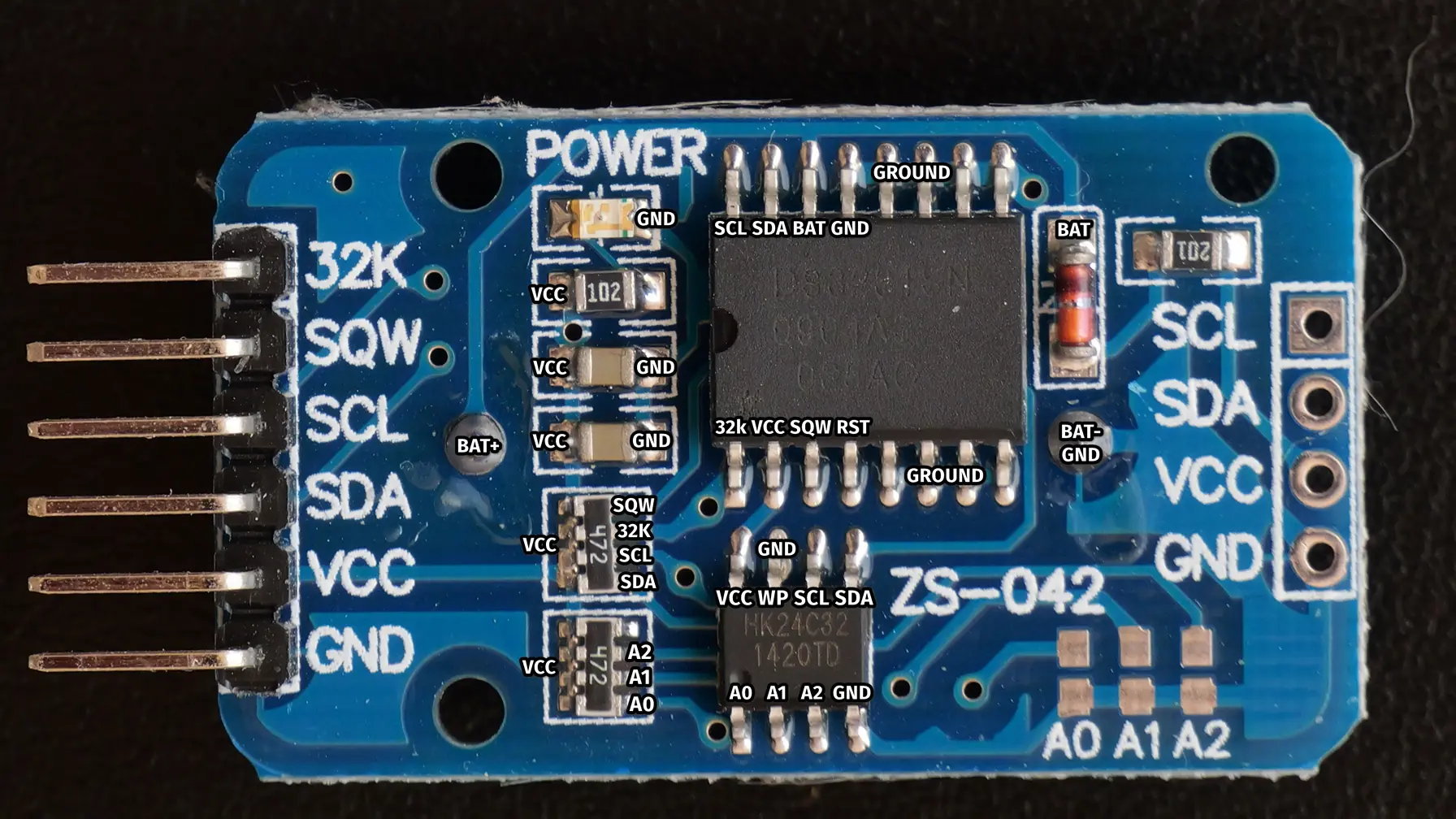 High resolution image of unmodified ZS-042 DS3231 RTC module with pin descriptions
So we need to disconnect three wires:
- battery charging (201 resistor, diode or trace)
- LED (102 resistor or trace between resistor and LED)
- trace between upmost pin of upper resistor network
And other important piece of puzzle seems to be this
- DS3231 RTC on ZS-042 module - if low power is important mentioning the need call wire.end() before setting RTC_VCC to ground.
and it seems very confusing that
1
DigitalWrite(SDA, LOW);
disables pull-up resistor instead of setting low state of the pin. This is because it’s actually configured as an input pin and DigitalWrite behaves differently.
Realization, added 2024-04-15
I disconnected int PIN pull up resistor. Now it seems that it works, but power consumption increased to 0.260/0.18mA depending on ADC enabled (was 0.23/0.15mA), which is weird. It does not depend on serial communication pins being connected (EDIT: actually it does, fraction of power - low microamps - goes trough communication pins)
Then I connected VCC pin of RTC module to Arduino and made a few adjustments to a code, especially routine that is responisble for sleep:
1
constexpr uint8_t RTC_VCC_PIN = 10;
This disables pull-up resistors on SDA and SCL line to prevent RTC from being accidentally powered by them and disables power to RTC which is now powered from pin 10 before sleep routine.
1
2
3
4
  Wire.end();
  digitalWrite(SDA, LOW);
  digitalWrite(SCL, LOW);
  digitalWrite(RTC_VCC_PIN, LOW);
This powers RTC again and re-enables I2C communication after wake up.
1
2
  digitalWrite(RTC_VCC_PIN, HIGH);
  Wire.begin();
Now power consumption dropped to 0.9mA or 97uA depening on multimeter range, which is the same as with RTC completely disconnected. Question is why. I haven’t touched this for two weeks now. All I changed a bit is ADC logic but I don’t think it had any effect.
At this point I may create other project to test it, which is easier as it does not need any wiring except USB to serial and code could be smaller.
Reducing power consumption of Arduino (2024-04-17)
I tried some tips mentioned in the Nick Gammon -=- Power saving techniques for microprocessors blog post, but with no luck. I’ve done everything before except disabling brown-out detection which saved roughly 15uA.
My Arduino Pro Mini is SparkFun model V13 from 2011 bought in 2016.
Removing LED
This is obvious first step that was done long time ago. Can be done either by cutting a trace or desoldering resistor.
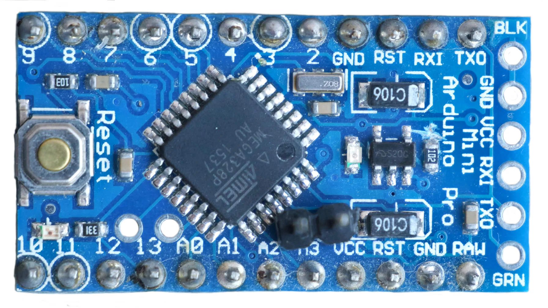 Arduino Pro Mini with interrupted trace to LED
Power down
1
2
3
4
5
6
7
8
9
10
11
12
#include <avr/sleep.h>

void setup()
{
  set_sleep_mode(SLEEP_MODE_PWR_DOWN);
  sleep_enable();
  sleep_cpu();
  // 182uA here
}

void loop()
{ }
Power down + ADC disable
1
2
3
4
5
6
7
8
9
10
11
12
13
14
15
#include <avr/sleep.h>

void setup()
{
   // Clear ADC_ENABLE bit in ADC status register A
   // The same current measurent with ADCSRA = 0
  ADCSRA &= (uint8_t)(~(1 << ADEN));
  set_sleep_mode(SLEEP_MODE_PWR_DOWN);
  sleep_enable();
  sleep_cpu();
  // 96.5-97.5uA with powering trough RAW pin or VCC pin by 3.3V
}

void loop()
{ }
Power down + ADC disable + BOD disable
1
2
3
4
5
6
7
8
9
10
11
12
13
14
15
16
17
18
19
20
21
22
#include <avr/sleep.h>

void setup()
{
  delay(10);

  ADCSRA &= (uint8_t)(~(1 << ADEN));

  set_sleep_mode (SLEEP_MODE_PWR_DOWN);
  noInterrupts ();           // timed sequence follows
  sleep_enable();

  // turn off brown-out enable in software
  MCUCR = bit (BODS) | bit (BODSE);  // turn on brown-out enable select
  MCUCR = bit (BODS);        // this must be done within 4 clock cycles of above
  interrupts ();             // guarantees next instruction executed
  sleep_cpu ();              // sleep within 3 clock cycles of above
  // 80uA here
}

void loop()
{ }
Power down + ADC disable + BOD disable + pins output&low
1
2
3
4
5
6
7
8
9
10
11
12
13
14
15
16
17
18
19
20
21
22
23
24
25
26
27
28
#include <avr/sleep.h>

void setup()
{
    for (byte i = 0; i <= A7; i++)
    {
      pinMode (i, OUTPUT);    // changed as per below
      digitalWrite (i, LOW);  //     ditto
    }

  delay(10);

  ADCSRA &= (uint8_t)(~(1 << ADEN));

  set_sleep_mode (SLEEP_MODE_PWR_DOWN);
  noInterrupts ();           // timed sequence follows
  sleep_enable();

  // turn off brown-out enable in software
  MCUCR = bit (BODS) | bit (BODSE);  // turn on brown-out enable select
  MCUCR = bit (BODS);        // this must be done within 4 clock cycles of above
  interrupts ();             // guarantees next instruction executed
  sleep_cpu ();              // sleep within 3 clock cycles of above
  // 77uA
}

void loop()
{ }
Summary
- ADC ~85uA
- BOD ~16uA
- Pins output&low ~3uA
However, setting pins to output and low reduces powers consumption when Arduino is not sleeping.
Here I cannot go lower other way than to desolder mysterious, unidentifiable S20G MicrOne ME6211 voltage regulator, which is not present in original SparkFun schematics (there should be Micrel MIC5205), which strongly suggest that this board is Chinese copy and also ATMega328 chip may be fake.
I tried other Arduino, got 75uA. When RX/TX pins are connected, measurement can differ by 1-2uA.
At this point last option is to either desolder voltage regulator or try bare ATMega328P chip.
Stuff learned
- Nothing is easy. Everything is hard
- Arduino and RTC module can survive reverse polarity at 3.3V (tested by accident -> it’s a good practise to use black wires for ground and red for vcc)
- Magic GRN pin is crucial for reliable uploads
- Voltcraft VC-175: It’s not possible to switch multimeter to microamps range, when current peaks exceed 10mA (e.g during the programming)
- Old links to Arduino Forum are either lost or without pictures, keep important pages archived.
- Youtube tutorials work better when results are not verified using multimeter (don’t trust everything)
- How I got to 150uA for both Arduino and RTC is a mystery.
- Using lambda function in interupt code is likely a mistake.
Further exploration
- Bare Arduino
- Remove voltage regulator (I have some backups)
TODO: remove lambda
Links
- The Cave Pearl Project -=- Using a $1 DS3231 Real-time Clock Module with Arduino
- heliosoph -=- Arduino powered by a capacitor - the start
- heliosoph -=- Arduino powered by a capacitor - first tests
- heliosoph -=- ArduinoISP: reading and writing fuses on ATmega328P
- heliosoph -=- Arduino powered by a capacitor - reducing consumption
- heliosoph -=- Arduino powered by a capacitor - optimized tests
- heliosoph -=- Instructions from the AVR power library for ATmega328P <avr/power.h> reduced to ATmega328P relevant functions.
- heliosoph -=- ATmega328P wakeup from sleep via interrupt
- heliosoph -=- Arduino powered by a capacitor - timing with RTC
heliosoph -=- Arduino powered by a capacitor - extending memory
- Nick Gammon -=- Temperature and humidity sensor - battery powered
- Nick Gammon -=- Power saving techniques for microprocessors
Kevin Darrah -=- Low Power Arduino! Deep Sleep Tutorial YouTube video
- Mods to DS3231 ZS-042 module for power control