ENG | Zephyr RTOS: SPI Flash
Battle with overlay and prj.conf files continues.
This article explores SPI flash configuration in Zephyr RTOS, a task that should take 30 minutes but may as well ruin your entire weekend.
If you’re here, you’ve probably also stared at error messages like undefined reference to __device_dts_ord_34 and wondered if you should have become a garbage collector instead. Welcome to the club.
Internal flash on XIAO nRF52840
Surprise. XIAO nRF52840 has internal flash, you can take zephyr/samples/drivers/spi_flash and it will work. Good starting point. Here is console output of slightly modified example:
1
2
3
4
5
6
7
8
9
10
11
12
13
14
15
Connected to MicroPython at COM11
Use Ctrl-] or Ctrl-x to exit this shell
*** Booting Zephyr OS build v4.1.0-5418-g98ba754013b0 ***
Flash size: 2097152 bytes (2.00 MB)
Write block size: 4 bytes
p25q16h@0 SPI flash testing
==========================

Perform test on single sector
Test 1: Flash erase
Flash erase succeeded!

Test 2: Flash write
Attempting to write 4 bytes
Data read matches data written. Good!!
Just for curiosity, relevant files are in zephyr/boards/seeed/xiao_ble/ and contain string qspi
1
2
3
4
5
6
7
8
9
10
11
12
13
14
15
16
17
18
19
20
21
22
&qspi {
    status = "okay";
    pinctrl-0 = <&qspi_default>;
    pinctrl-1 = <&qspi_sleep>;
    pinctrl-names = "default", "sleep";
    p25q16h: p25q16h@0 {
        compatible = "nordic,qspi-nor";
        reg = <0>;
        sck-frequency = <104000000>;
        quad-enable-requirements = "S2B1v1";
        jedec-id = [85 60 15];
        sfdp-bfp = [
            e5 20 f1 ff  ff ff ff 00  44 eb 08 6b  08 3b 80 bb
            ee ff ff ff  ff ff 00 ff  ff ff 00 ff  0c 20 0f 52
            10 d8 08 81
        ];
        size = <16777216>;
        has-dpd;
        t-enter-dpd = <3000>;
        t-exit-dpd = <8000>;
    };
};
1
2
3
4
5
6
7
8
9
10
11
12
13
14
15
16
17
18
19
20
21
22
23
24
25
26
    qspi_default: qspi_default {
        group1 {
            psels = <NRF_PSEL(QSPI_SCK, 0, 21)>,
                <NRF_PSEL(QSPI_IO0, 0, 20)>,
                <NRF_PSEL(QSPI_IO1, 0, 24)>,
                <NRF_PSEL(QSPI_IO2, 0, 22)>,
                <NRF_PSEL(QSPI_IO3, 0, 23)>,
                <NRF_PSEL(QSPI_CSN, 0, 25)>;
        };
    };

    qspi_sleep: qspi_sleep {
        group1 {
            psels = <NRF_PSEL(QSPI_SCK, 0, 21)>,
                <NRF_PSEL(QSPI_IO0, 0, 20)>,
                <NRF_PSEL(QSPI_IO1, 0, 24)>,
                <NRF_PSEL(QSPI_IO2, 0, 22)>,
                <NRF_PSEL(QSPI_IO3, 0, 23)>;
            low-power-enable;
        };
        group2 {
            psels = <NRF_PSEL(QSPI_CSN, 0, 25)>;
            low-power-enable;
            bias-pull-up;
        };
    };
Easy!
XIAO RP2040 and External flash
Physical connection
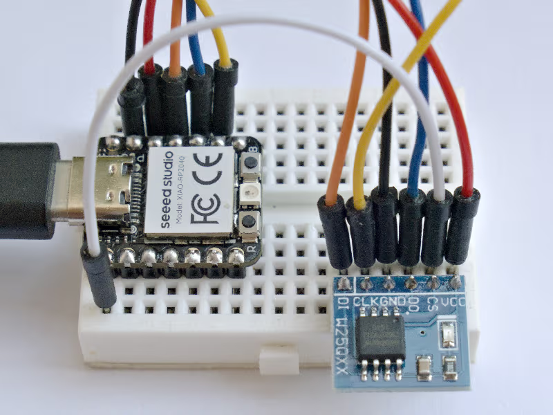
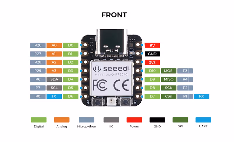
| XIAO RP2040 | Flash | Note |
|---|---|---|
| D0 / P26 / Left 1 | CS | Chip select |
| GND / Right 2 | GND | |
| 3V3 / Right 3 | VCC | |
| D10 / MOSI / P3 / Right 4 | DI | Master Out Slave In -> Data In |
| D9 / MISO / P4 / Right 5 | DO | Master In Slave Out <- Data Out |
| D8 / SCK / P2 / Right 6 | CLK | Clock |
Getting started with SPI
Hmm. This will be harder (actually much harder). There is also internal flash, but I assume it’s meant for storing firmware and I don’t want to mess with it (for now). Let’s connect external one to standard SPI pins and pin D0 for chip select.
There is relevant Raspberry Pi Pico SPI documentation and files for default SPI configuration for XIAO RP2040 which can be modified for Raspberry Pi Pico.
1
2
3
4
5
6
&spi0 {
    status = "okay";
    pinctrl-0 = <&spi0_default>;
    pinctrl-names = "default";
    clock-frequency = <DT_FREQ_M(8)>;
};
1
2
3
4
5
6
7
8
9
10
11
12
    spi0_default: spi0_default {
        group1 {
            pinmux = <SPI0_TX_P3>;
        };
        group2 {
            pinmux = <SPI0_RX_P4>;
            input-enable;
        };
        group3 {
            pinmux = <SPI0_SCK_P2>;
        };
    };
Curiously, this pinctrl part is completely different from XIAO nRF52840 example above.
Creating auxiliary files
Why not to get inspiration from files above and Raspberry Pi Pico SPI Zephyr documentation ?
1
2
3
4
5
6
7
8
9
10
11
12
13
14
15
16
17
18
&spi0 {
    // Array of CSEL pins
    cs-gpios = <&gpio0 26 GPIO_ACTIVE_LOW>;
    // Devices corresponding to CSEL pins
    status = "okay";
    w25q32: w25q32@0 {
        compatible = "jedec,spi-nor";
        reg = <0>;
        spi-max-frequency = <8000000>;
        status = "okay";
        /*
        size = <0x400000>;
        has-dpd;
        t-enter-dpd = <3000>;
        t-exit-dpd = <30000>;
        */
    };
};
1
2
3
4
5
CONFIG_STDOUT_CONSOLE=y
CONFIG_FLASH=y
CONFIG_SPI=y
CONFIG_SPI_NOR=y
CONFIG_CBPRINTF_FP_SUPPORT=y # Support for printf("%f", ...);
The file above is not final
Mysterious compile error: jedec-id
1
2
3
C:/dev-zephyr/zephyrproject/zephyr/include/zephyr/toolchain/gcc.h:87:36: error: static assertion failed: "jedec,spi-nor jedec-id required for non-runtime SFDP"
   87 | #define BUILD_ASSERT(EXPR, MSG...) _Static_assert((EXPR), "" MSG)
      |                                    ^~~~~~~~~~~~~~
This is hidden somewhere above 200 other error lines
The Problem
Your device tree overlay is missing the jedec-id property, which is required for SPI NOR flash devices when not using runtime SFDP detection.
How to Find the Correct jedec-id
The jedec-id is a 3-byte identifier that’s specific to each flash chip. Here are common ones:
Winbond W25Q series:
- W25Q32: [ef 40 16]
- W25Q64: [ef 40 17]
- W25Q128: [ef 40 18]
Macronix MX25L series:
- MX25L3206E: [c2 20 16]
- MX25L6406E: [c2 20 17]
Micron/ST M25P series:
- M25P32: [20 20 16]
- M25P64: [20 20 17]
GigaDevice GD25Q series:
- GD25Q32: [c8 40 16]
- GD25Q64: [c8 40 17]
Alternative: Enable Runtime SFDP
If you don’t know the exact jedec-id, you can enable runtime SFDP detection in your prj.conf:
1
CONFIG_SPI_NOR_SFDP_RUNTIME=y
This is stupidly bad error reporting, but it can be worse.
Mysterious error: __device_dts_ord_34
1
c:/users/pavel/zephyr-sdk-0.17.0/arm-zephyr-eabi/bin/../lib/gcc/arm-zephyr-eabi/12.2.0/../../../../arm-zephyr-eabi/bin/ld.bfd.exe: zephyr/drivers/flash/libdrivers__flash.a(spi_nor.c.obj):(.rodata.spi_nor_0_config+0xc): undefined reference to `__device_dts_ord_34'
This error is actually documented in Zephyr’s Device Tree Troubleshooting Guide
It suggests to look into the following file and to try to realize what the error really means.
Note: the following code is shortened, original file has tens thousands lines of code. I searched for occurences of number 34.
1
2
3
4
5
6
7
8
9
10
11
12
13
14
15
16
17
18
19
20
21
22
23
24
25
26
27
28
29
30
31
32
33
/*
 * Generated by gen_defines.py
 *
 * DTS input file:
 *   C:/dev-zephyr/zephyrproject/my_projects/spi-flash/build/zephyr/zephyr.dts.pre
 *
 * Directories with bindings:
 *   $ZEPHYR_BASE\dts\bindings
 *
 * Node dependency ordering (ordinal and path):
 *   0   /
 *   1   /aliases
 *   2   /chosen
 *   3   /connector
 *   4   /soc

 *   33  /soc/gpio@40014000
 *   34  /soc/gpio@40014000/gpio-port@0
 */


/* Node's dependency ordinal: */
#define DT_N_S_soc_S_gpio_40014000_ORD 33
#define DT_N_S_soc_S_gpio_40014000_ORD_STR_SORTABLE 00033

/* Ordinals for what this node depends on directly: */
#define DT_N_S_soc_S_gpio_40014000_REQUIRES_ORDS \
    4, /* /soc */ \
    26, /* /soc/interrupt-controller@e000e100 */

/* Ordinals for what depends directly on this node: */
#define DT_N_S_soc_S_gpio_40014000_SUPPORTS_ORDS \
    34, /* /soc/gpio@40014000/gpio-port@0 */
Yeah. One or two hours later (chatgpt was not much helpful) I realized I need to put yet another line into prj.conf
1
CONFIG_GPIO=y
Now I’m starting to hate Zephyr, cause error messages are cryptic and it’s basically impossible to guess what I need to enable in config to make stuff work.
Wait … why does everything works with XIAO nRF52840?
I turns out there are mysterious files, that enable various driver for specific board.
1
2
3
4
5
6
7
8
9
10
11
12
13
14
15
16
17
18
19
20
# SPDX-License-Identifier: Apache-2.0

CONFIG_RESET=y

# Enable UART driver
CONFIG_SERIAL=y
CONFIG_UART_INTERRUPT_DRIVEN=y

# Enable console
CONFIG_CONSOLE=y
CONFIG_UART_CONSOLE=y

# Enable clock control by default
CONFIG_CLOCK_CONTROL=y

# Code partition needed to target the correct flash range
CONFIG_USE_DT_CODE_PARTITION=y

# Output UF2 by default, native bootloader supports it.
CONFIG_BUILD_OUTPUT_UF2=y
1
2
3
4
5
6
7
8
9
10
11
12
13
14
15
16
17
18
19
20
# SPDX-License-Identifier: Apache-2.0

# Enable MPU
CONFIG_ARM_MPU=y

# Enable hardware stack protection
CONFIG_HW_STACK_PROTECTION=y

# Enable GPIO
CONFIG_GPIO=y

# Enable UART driver
CONFIG_SERIAL=y

# Enable console
CONFIG_CONSOLE=y

# Build UF2 by default, supported by the Adafruit nRF52 Bootloader
CONFIG_BUILD_OUTPUT_UF2=y
CONFIG_USE_DT_CODE_PARTITION=y
Well. Great. Similar mystery to why one board uses console over serial pins and other over serial-via-usb.
1
2
3
4
5
6
7
8
9
10
11
12
13
14
15
16
17
18
19
(.venv) PS C:\dev-zephyr\zephyrproject\my_projects\spi-flash> west build  -b xiao_rp2040 -S cdc-acm-console -- -DCONFIG_USB_DEVICE_INITIALIZE_AT_BOOT=y
(.venv) PS C:\dev-zephyr\zephyrproject\my_projects\spi-flash> cp .\build\zephyr\zephyr.uf2 e:
(.venv) PS C:\dev-zephyr\zephyrproject\my_projects\spi-flash> mpremote connect COM16
Connected to MicroPython at COM16
Use Ctrl-] or Ctrl-x to exit this shell
*** Booting Zephyr OS build v4.1.0-5418-g98ba754013b0 ***
Flash size: 4194304 bytes (4.00 MB)
Write block size: 1 bytes

w25q32@0 SPI flash testing
==========================

Perform test on single sector
Test 1: Flash erase
Flash erase succeeded!

Test 2: Flash write
Attempting to write 4 bytes
Data read matches data written. Good!!
The final prj.conf for XIAO RP2040
1
2
3
4
5
6
7
8
9
10
CONFIG_STDOUT_CONSOLE=y
CONFIG_FLASH=y
CONFIG_SPI=y
CONFIG_SPI_NOR=y
#CONFIG_FLASH_JESD216=y
#CONFIG_FLASH_JESD216_API=y
CONFIG_CBPRINTF_FP_SUPPORT=y
# Detect JEDEC ID at runtime, otherwise it must be in prj.conf
CONFIG_SPI_NOR_SFDP_RUNTIME=y
CONFIG_GPIO=y
Addendum: reading JEDEC ID in MicroPython
This code can be pasted into MicroPython’s console, just make sure pin numbers match your board.
1
2
3
4
5
6
7
8
9
10
11
12
13
14
15
16
17
18
19
20
21
22
23
24
25
26
27
28
29
30
from machine import Pin, SPI
import time

# Initialize SPI and CS pin
# Adjust pin numbers for your board
spi = SPI(0, baudrate=800000, sck=Pin(2), mosi=Pin(3), miso=Pin(4))
cs  = Pin(26, Pin.OUT, value=1)  # CS high = inactive

def spi_flash_read_jedec_id():
    """Read JEDEC ID from SPI flash chip"""
    cs.value(0)        # Select chip
    time.sleep_us(1)   # Small delay

    # Send JEDEC ID command (0x9F) and read 3 bytes
    buf = bytearray(4)
    spi.write_readinto(b'\x9F\x00\x00\x00', buf)

    cs.value(1)        # Deselect chip

    # Extract the 3-byte ID (skip first byte which is echo of command)
    jedec_id = buf[1:4]
    return jedec_id

# Read and display JEDEC ID
try:
    jedec_id = spi_flash_read_jedec_id()
    print(f"JEDEC ID: {jedec_id.hex()}")
    print(f"JEDEC ID: [{jedec_id[0]:02x} {jedec_id[1]:02x} {jedec_id[2]:02x}]")
except Exception as e:
    print(f"Error reading JEDEC ID: {e}")
1
2
JEDEC ID: ef4016
JEDEC ID: [ef 40 16]
Final words
The following article is about building data logger sort of on top of this one and using LittleFS, which is quite easy - but as always, things can go horribly wrong.
Links
- Data logger base / LittleFS Next article mentioning LittleFS
- GitHub LittleFS example Zephyr shell commands for interacting with LittleFS
- nRF52840 bootloader recovery because things can go wrong
TODOs:
- Using internal Flash region on Raspberry Pi Pico, configs for Raspberry Pi Pico
- Accessing flash data (Raspberry Pi 3B + external flash?)