ENG | Zephyr RTOS: The story of exploring I2C, configs and overlays
A journey through Zephyr RTOS I2C configuration challenges, from working examples to debugging pull-up resistor issues on Raspberry Pi Pico.
I wanted to do something really simple. Use RTC with various boards. It worked fine with XIAO nRF52840 + Extension Board. So I decided to try Raspberry Pi Pico.
This was a nightmare, because I2C pull-up resistors are not being enabled by default.
Notes are mostly in chronological order, including failures and sub-optimal commands at the start, changing as I learned.
RTC example using XIAO nRF52840 + Expansion Board
Files
src/main.c
1
2
3
4
5
6
7
8
9
10
11
12
13
14
15
16
17
18
19
20
21
22
23
24
25
26
27
28
29
30
31
32
33
34
35
36
37
38
39
40
41
42
43
44
45
46
47
48
49
50
51
52
53
54
55
56
57
58
59
60
61
62
63
64
65
66
#include <zephyr/kernel.h>
#include <zephyr/device.h>
#include <zephyr/drivers/rtc.h>
/* Defined in
* 1. ~/zephyrproject/zephyr/boards/shields/seeed_xiao_expansion_board/seeed_xiao_expansion_board.overlay
* 2. rpi_pico.overlay
*/
const struct device *const rtc = DEVICE_DT_GET(DT_ALIAS(rtc));
static int set_date_time(const struct device *rtc)
{
int ret = 0;
struct rtc_time tm = {
.tm_year = 25,
.tm_mon = 06,
.tm_mday = 13,
.tm_hour = 1,
.tm_min = 23,
.tm_sec = 45,
};
ret = rtc_set_time(rtc, &tm);
if (ret < 0) {
printk("Cannot write date time: %d\n", ret);
return ret;
}
return ret;
}
int main(void)
{
/* Get the RTC device */
if (!device_is_ready(rtc)) {
printk("RTC device not ready\n");
return -1;
}
printk("RTC initialized\n");
/* rtc_get_time returns -61 when time is invalid */
/* set_date_time(rtc); */
while (1) {
struct rtc_time current_time;
/* Read current time from RTC */
const int ret = rtc_get_time(rtc, ¤t_time);
if (ret < 0) {
printk("Failed to read RTC time, code=%d\n", ret);
} else {
/* Display the time */
printk("Time: %04d-%02d-%02d %02d:%02d:%02d\n",
current_time.tm_year + 2000,
current_time.tm_mon,
current_time.tm_mday,
current_time.tm_hour,
current_time.tm_min,
current_time.tm_sec);
}
k_sleep(K_SECONDS(2));
}
return 0;
}
Interesting line is DEVICE_DT_GET(DT_ALIAS(rtc)); and there must be alias rtc for your board in *.overlay file. More on that later.
Sadly, perhaps there is some RTC specific code - months are saved as 1-12, years as 0-99. For some RTCs year could be set starting from 1900 and month as 0-11. I don’t know. I’ve seen this in default example when I studied parts of the code.
CMakeLists.txt
1
2
3
4
cmake_minimum_required(VERSION 3.20.0)
find_package(Zephyr REQUIRED HINTS $ENV{ZEPHYR_BASE})
project(rtc)
target_sources(app PRIVATE src/main.c)
Nothing interesting here. I assume that project(rtc) line is necessary and target must be named app. Maybe not, but it causes problems, so I’ll stick with defaults.
prj.conf
1
CONFIG_RTC=y
Compilation
With these files, we can compile, upload and run it.
1
2
3
4
5
6
7
8
9
10
11
12
13
14
15
(.venv) [pavel@marten -=- ~/zephyrproject/my_projects/rtc_pcf8563_api]$ west build -p -b xiao_ble/nrf52840 --shield seeed_xiao_expansion_board
(.venv) [pavel@marten -=- ~/zephyrproject/my_projects/rtc_pcf8563_api]$ udisksctl mount -b /dev/sda
(.venv) [pavel@marten -=- ~/zephyrproject/my_projects/rtc_pcf8563_api]$ cp build/zephyr/zephyr.uf2 /run/media/pavel/XIAO-SENSE
(.venv) [pavel@marten -=- ~/zephyrproject/my_projects/rtc_pcf8563_api]$ mpremote a1
Connected to MicroPython at /dev/ttyACM1
Use Ctrl-] or Ctrl-x to exit this shell
*** Booting Zephyr OS build v4.1.0-5582-g2c5c0e24e8fd ***
RTC initialized
Time: 2025-06-14 08:55:08
Time: 2025-06-14 08:55:10
Time: 2025-06-14 08:55:12
Time: 2025-06-14 08:55:14
Time: 2025-06-14 08:55:16
Time: 2025-06-14 08:55:18
Time: 2025-06-14 08:55:20
It magically works. Actually. Magic is hidden in zephyr/boards/shields/seeed_xiao_expansion_board/seeed_xiao_expansion_board.overlay
The code above works, only if RTC has valid time. Which is a problem if there is not battery backup. Then it returns error code
-61.
It’s not always that easy. Wait for Raspberry Pi Pico
RTC example using XIAO RP2040 + Expansion Board
As we shown before, with hello world example, output goes to serial port by default. Not to USB serial. So let’s try to combine previous examples and command line parameters
Files (extra)
1
2
3
4
5
6
7
8
9
CONFIG_USB_DEVICE_STACK=y
CONFIG_USB_DEVICE_PRODUCT="Zephyr USB console"
CONFIG_USB_CDC_ACM=y
# We don't want extra code for that in main()
CONFIG_USB_DEVICE_INITIALIZE_AT_BOOT=y
CONFIG_USB_DEVICE_PID=0x0004
CONFIG_SERIAL=y
CONFIG_CONSOLE=y
CONFIG_UART_CONSOLE=y
1
2
3
4
5
6
7
8
9
10
/ {
    chosen {
        zephyr,console = &usb_cdc;
    };
};
&zephyr_udc0 {
    usb_cdc: usb_cdc_0 {
        compatible = "zephyr,cdc-acm-uart";
    };
};
Compilation
1
2
3
4
west build --pristine --board xiao_rp2040 --shield seeed_xiao_expansion_board -- -DOVERLAY_CONFIG="usb.conf" -DDTC_OVERLAY_FILE="usb.overlay"
udisksctl mount -b /dev/sda1
cp build/zephyr/zephyr.uf2 /run/media/pavel/RPI-RP2
mpremote a1
1
2
3
4
5
6
7
8
9
10
Connected to MicroPython at /dev/ttyACM1
Use Ctrl-] or Ctrl-x to exit this shell
*** Booting Zephyr OS build v4.1.0-5582-g2c5c0e24e8fd ***
RTC initialized
Time: 2025-06-14 19:28:52
Time: 2025-06-14 19:28:54
Time: 2025-06-14 19:28:56
Time: 2025-06-14 19:28:58
Time: 2025-06-14 19:29:00
Time: 2025-06-14 19:29:02
Great!
I2C Scanner
Files
1
2
3
4
5
6
7
8
9
10
11
12
13
14
15
16
17
18
19
20
21
22
23
24
25
26
27
28
29
30
31
32
33
34
35
36
37
38
39
40
41
42
43
44
45
46
47
48
49
50
51
52
53
54
55
56
57
58
59
60
61
62
63
64
65
66
67
68
69
70
71
72
#include <zephyr/kernel.h>
#include <zephyr/device.h>
#include <zephyr/drivers/i2c.h>
#include <zephyr/sys/printk.h>

//#define I2C_DEV_LABEL DT_LABEL(DT_NODELABEL(i2c0)) // adjust if needed
#define CONFIG_I2C_SCAN_ADDR_START 0x08
#define CONFIG_I2C_SCAN_ADDR_STOP  0x77
//const struct device *i2c_dev = device_get_binding(I2C_DEV_LABEL);

static const struct device *i2c_dev = DEVICE_DT_GET(DT_ALIAS(my_i2c));

int main(void)
{
    k_sleep(K_SECONDS(5));
    if (!i2c_dev) {
        printk("I2C: Device driver not found.\n");
        return -1;
    }

    printk("*** I2C scanner started ***\n");
    printk("Board:           %s\n", CONFIG_BOARD);
    printk("I2C device:      %s\n", i2c_dev->name);

    /* Print pin information if available in devicetree */

    if (!device_is_ready(i2c_dev)) {
        printk("I2C device not ready\n");
        return -1;
    }

    printk("Scanning I2C bus...\n\n");

    printk("    | 0x00 0x01 0x02 0x03 0x04 0x05 0x06 0x07 0x08 0x09 0x0a 0x0b 0x0c 0x0d 0x0e 0x0f |\n");
    printk("----|---------------------------------------------------------------------------------");

    uint8_t error = 0u;
    uint8_t dst;
    uint8_t i2c_dev_cnt = 0;
    struct i2c_msg msgs[1];
    msgs[0].buf = &dst;
    msgs[0].len = 1U;
    msgs[0].flags = I2C_MSG_WRITE | I2C_MSG_STOP;

    /* Use the full range of I2C address for display purpose */
    for (uint16_t x = 0; x <= 0x7f; x++) {
        /* New line every 0x10 address */
        if (x % 0x10 == 0) {
            printk("|\n0x%02x| ",x);
        }
        /* Range the test with the start and stop value configured in the kconfig */
        if (x >= CONFIG_I2C_SCAN_ADDR_START && x <= CONFIG_I2C_SCAN_ADDR_STOP)	{
            /* Send the address to read from */
            error = i2c_transfer(i2c_dev, &msgs[0], 1, x);
                /* I2C device found on current address */
                if (error == 0) {
                    printk("0x%02x ",x);
                    ++i2c_dev_cnt;
                }
                else {
                    printk(".... ");
                }
        } else {
            /* Scan value out of range, not scanned */
            printk("     ");
        }
        k_sleep(K_MSEC(10));
    }
    printk("|\n");
    printk("\nI2C device(s) found on the bus: %d\nScanning done.\n\n", i2c_dev_cnt);
    return 0;
}
1
2
3
4
cmake_minimum_required(VERSION 3.20.0)
find_package(Zephyr REQUIRED HINTS $ENV{ZEPHYR_BASE})
project(i2c_scan)
target_sources(app PRIVATE src/main.c)
1
2
3
4
5
CONFIG_I2C=y
# Useful for debugging
#CONFIG_LOG=y
#CONFIG_RTC_LOG_LEVEL_DBG=y
#CONFIG_I2C_LOG_LEVEL_DBG=y
Now overlay files defining my_i2c alias for various boards. For XIAO RP2040 and nRF52840 they are identical.
1
2
3
4
5
/ {
    aliases {
        my-i2c = &i2c1;
    };
};
1
2
3
4
5
/ {
    aliases {
        my-i2c = &i2c1;
    };
};
Add usb.* from previous project
Compiling
Here I don’t know why i need to specify xiao_rp2040.overlay.
1
2
3
4
5
6
7
8
9
10
11
12
13
14
15
16
17
18
19
20
21
22
23
24
25
26
27
28
29
30
31
32
33
34
35
36
37
38
39
40
41
42
43
44
45
(.venv) [pavel@marten -=- ~/zephyrproject/my_projects/i2c_scan]$ west build --pristine --board xiao_rp2040  -- -DOVERLAY_CONFIG="usb.conf" -DDTC_OVERLAY_FILE="usb.overlay;xiao_rp2040.overlay"
...
-- Found BOARD.dts: /home/pavel/zephyrproject/zephyr/boards/seeed/xiao_rp2040/xiao_rp2040.dts
-- Found devicetree overlay: usb.overlay
-- Found devicetree overlay: xiao_rp2040.overlay
-- Generated zephyr.dts: /home/pavel/zephyrproject/my_projects/i2c_scan/build/zephyr/zephyr.dts
...
Loaded configuration '/home/pavel/zephyrproject/zephyr/boards/seeed/xiao_rp2040/xiao_rp2040_defconfig'
Merged configuration '/home/pavel/zephyrproject/my_projects/i2c_scan/prj.conf'
Merged configuration '/home/pavel/zephyrproject/my_projects/i2c_scan/usb.conf'
Configuration saved to '/home/pavel/zephyrproject/my_projects/i2c_scan/build/zephyr/.config'
...

(.venv) [pavel@marten -=- ~/zephyrproject/my_projects/i2c_scan]$ udisksctl mount -b /dev/sda1
==== AUTHENTICATING FOR org.freedesktop.udisks2.filesystem-mount ====
Authentication is required to mount RPI RP2 (/dev/sda1)
Authenticating as: Pavel Perina (pavel)
Password:
==== AUTHENTICATION COMPLETE ====
Mounted /dev/sda1 at /run/media/pavel/RPI-RP2

(.venv) [pavel@marten -=- ~/zephyrproject/my_projects/i2c_scan]$ cp build/zephyr/zephyr.uf2 /run/media/pavel/RPI-RP2

(.venv) [pavel@marten -=- ~/zephyrproject/my_projects/i2c_scan]$ mpremote a1
Connected to MicroPython at /dev/ttyACM1
Use Ctrl-] or Ctrl-x to exit this shell
*** Booting Zephyr OS build v4.1.0-5582-g2c5c0e24e8fd ***
*** I2C scanner started ***
Board:           xiao_rp2040
I2C device:      i2c@40048000
Scanning I2C bus...

    | 0x00 0x01 0x02 0x03 0x04 0x05 0x06 0x07 0x08 0x09 0x0a 0x0b 0x0c 0x0d 0x0e 0x0f |
----|---------------------------------------------------------------------------------|
0x00|                                         .... .... .... .... .... .... .... .... |
0x10| .... .... .... .... .... .... .... .... .... .... .... .... .... .... .... .... |
0x20| .... .... .... .... .... .... .... .... .... .... .... .... .... .... .... .... |
0x30| .... .... .... .... .... .... .... .... .... .... .... .... 0x3c .... .... .... |
0x40| .... .... .... .... .... .... .... .... .... .... .... .... .... .... .... .... |
0x50| .... 0x51 .... .... .... .... .... .... .... .... .... .... .... .... .... .... |
0x60| .... .... .... .... .... .... .... .... .... .... .... .... .... .... .... .... |
0x70| .... .... .... .... .... .... .... ....                                         |

I2C device(s) found on the bus: 2
Scanning done.
Fast commands
1
2
3
4
5
6
7
8
9
10
11
12
13
14
# XIAO RP2040
west build --pristine --board xiao_rp2040  -- -DOVERLAY_CONFIG="usb.conf" -DDTC_OVERLAY_FILE="usb.overlay;xiao_rp2040.overlay"
# Alternative (better)
west build -p -b xiao_rp2040 -S cdc-acm-console -- -DCONFIG_USB_DEVICE_INITIALIZE_AT_BOOT=y
udisksctl mount -b /dev/sda1
cp build/zephyr/zephyr.uf2 /run/media/pavel/RPI-RP2
# NOTE: a1 is not needed if there is one serial port
mpremote a1
# XIAO nRF52840 (does not need usb-serial and overlay is found automatically)
west build -p -b xiao_ble/nrf52840 --shield seeed_xiao_expansion_board
udisksctl mount -b /dev/sda1
#cp build/zephyr/zephyr.uf2 /run/media/pavel/XIAO-SENSE
west flash -r uf2 # Let's learn something new
mpremote a1
Next level: Raspberry Pi Pico (FAILURE)
This part describes like six hours of wasted time trying to debug I2C communication on Raspberry Pi Pico. Surprisingly XIAO RP2040 works, but I could not realize why Raspberry Pi Pico I2C scan gives false positives and, contrary, Raspberry Pi Pico 2 cannot find anything at all.
Nonetheless further text somewhat shows how configuration (overlays) work and sheds some light on the process how I created my own overlay files.
This can be skipped.
Good. Now we can have something like this.
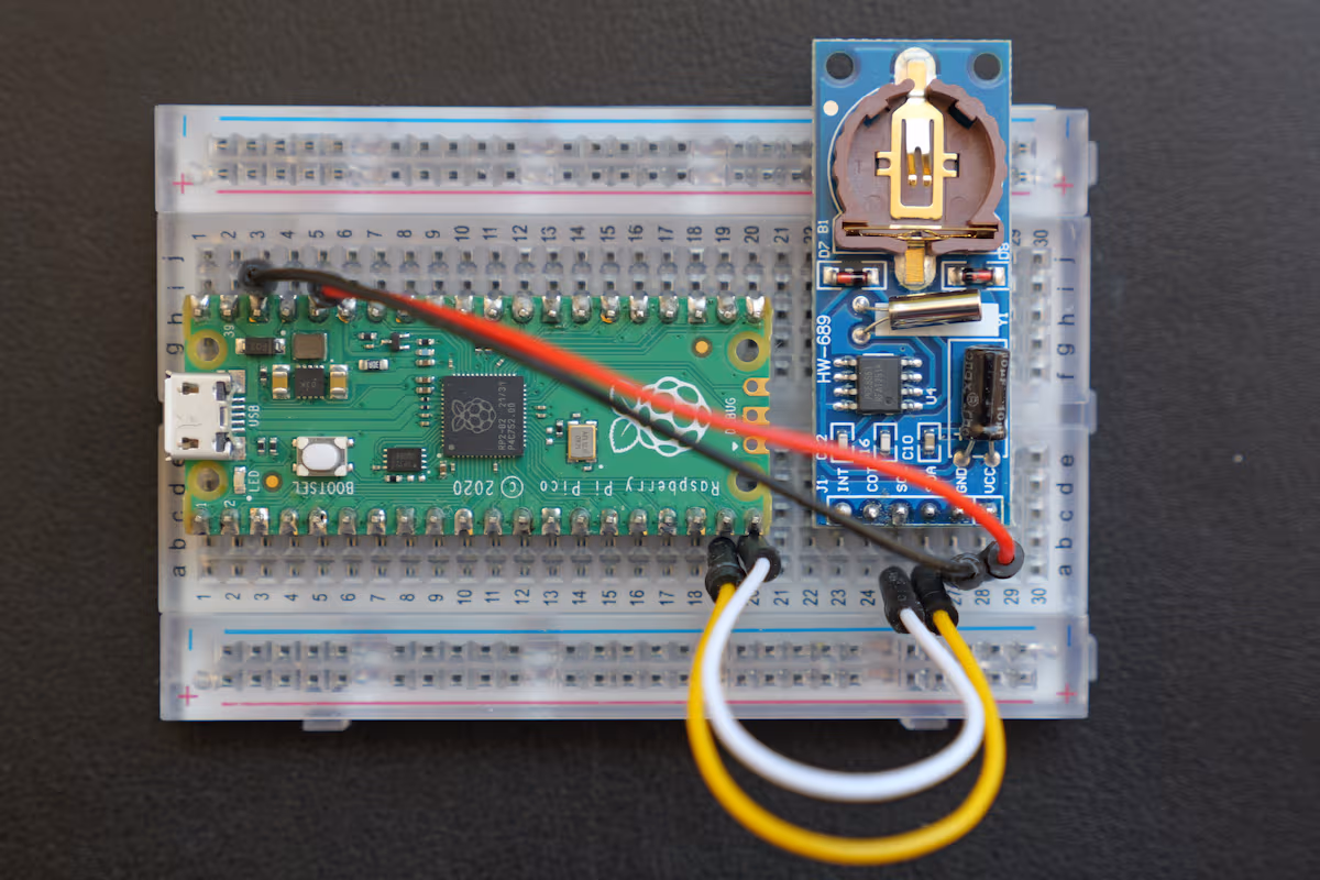 Raspberry Pi Pico with RTC connected to I2C1 SDA=GP14, SCL=GP15
There are only two problems:
- Examples have to compile
- Examples have to work
- We have 12 possibilities where to connect I2C bus
It should compile like this
1
2
3
4
west build --pristine --board rpi_pico  -- -DOVERLAY_CONFIG="usb.conf" -DDTC_OVERLAY_FILE="usb.overlay;rpi_pico.overlay"
udisksctl mount -b /dev/sda1
cp build/zephyr/zephyr.uf2 /run/media/pavel/RPI-RP2
mpremote a1
NOTE: I’ve spend some significant time getting there. Source code is very sensitive to using various defines. For example
#define MY_I2C i2c1and usingMY_I2Cin source code. If i2c1 is disabled in device tree, it won’t compile.
And output should not look like this
1
2
3
4
5
6
7
8
9
10
11
12
13
14
15
16
17
18
 Connected to MicroPython at /dev/ttyACM1
Use Ctrl-] or Ctrl-x to exit this shell
*** Booting Zephyr OS build v4.1.0-5582-g2c5c0e24e8fd ***
*** I2C scanner started ***
Board:           rpi_pico
I2C device:      i2c@40048000
Scanning I2C bus...

    | 0x00 0x01 0x02 0x03 0x04 0x05 0x06 0x07 0x08 0x09 0x0a 0x0b 0x0c 0x0d 0x0e 0x0f |
----|---------------------------------------------------------------------------------|
0x00|                                         0x08 0x09 0x0a 0x0b 0x0c 0x0d 0x0e 0x0f |
0x10| 0x10 0x11 0x12 0x13 0x14 0x15 0x16 0x17 0x18 0x19 0x1a 0x1b 0x1c 0x1d 0x1e 0x1f |
0x20| 0x20 0x21 0x22 0x23 0x24 0x25 0x26 0x27 0x28 0x29 0x2a 0x2b 0x2c 0x2d 0x2e 0x2f |
0x30| 0x30 0x31 0x32 0x33 0x34 0x35 0x36 0x37 0x38 0x39 0x3a 0x3b 0x3c 0x3d 0x3e 0x3f |
0x40| 0x40 0x41 0x42 0x43 0x44 0x45 0x46 0x47 0x48 0x49 0x4a 0x4b 0x4c 0x4d 0x4e 0x4f |
0x50| 0x50 0x51 0x52 0x53 0x54 0x55 0x56 0x57 0x58 0x59 0x5a 0x5b 0x5c 0x5d 0x5e 0x5f |
0x60| 0x60 0x61 0x62 0x63 0x64 0x65 0x66 0x67 0x68 0x69 0x6a 0x6b 0x6c 0x6d 0x6e 0x6f |
0x70| 0x70 0x71 0x72 0x73 0x74 0x75 0x76 0x77
Here it got stuck. By the way, I wrote I2C scanner using Google and LLMs only to debug rtc example. So far, rpi_pico.overlay file looks like this:
1
2
3
4
5
6
7
8
9
10
11
12
13
14
15
16
17
18
19
20
21
22
/ {
    aliases {
        my-i2c = &i2c1;
    };
};

&pinctrl {
    i2c1_custom: i2c1_custom {
        group1 {
            pinmux= <I2C1_SDA_P14>, <I2C1_SCL_P15>;
            input-enable;
            input-schmitt-enable;
        };
    };
};

&i2c1 {
    status = "okay";
    pinctrl-0 = <&i2c1_custom>;
    pinctrl-names = "default";
    clock-frequency = <I2C_BITRATE_STANDARD>;
};
Now it’s time to play with these files:
~/zephyrproject/my_projects/i2c_scan/build/zephyr/zephyr.dts
Final, compiled device tree1 2 3 4 5 6 7 8 9 10 11 12 13 14 15 16 17 18 19 20 21 22 23 24 25 26 27 28 29 30 31 32 33 34 35 36 37 38
i2c1: pico_i2c1: i2c@40048000 { compatible = "raspberrypi,pico-i2c", "snps,designware-i2c"; /* in zephyr/dts/arm/raspberrypi/rpi_pico/rp2040.dtsi:332 */ #address-cells = < 0x1 >; /* in zephyr/dts/arm/raspberrypi/rpi_pico/rp2040.dtsi:333 */ #size-cells = < 0x0 >; /* in zephyr/dts/arm/raspberrypi/rpi_pico/rp2040.dtsi:334 */ reg = < 0x40048000 0x1000 >; /* in zephyr/dts/arm/raspberrypi/rpi_pico/rp2040.dtsi:335 */ resets = < &reset 0x4 >; /* in zephyr/dts/arm/raspberrypi/rpi_pico/rp2040.dtsi:336 */ clocks = < &clocks 0x5 >; /* in zephyr/dts/arm/raspberrypi/rpi_pico/rp2040.dtsi:337 */ interrupts = < 0x18 0x3 >; /* in zephyr/dts/arm/raspberrypi/rpi_pico/rp2040.dtsi:338 */ interrupt-names = "i2c1"; /* in zephyr/dts/arm/raspberrypi/rpi_pico/rp2040.dtsi:339 */ status = "okay"; /* in my_projects/i2c_scan/build/zephyr/rpi_pico.overlay:18 */ pinctrl-0 = < &i2c1_custom >; /* in my_projects/i2c_scan/build/zephyr/rpi_pico.overlay:19 */ pinctrl-names = "default"; /* in my_projects/i2c_scan/build/zephyr/rpi_pico.overlay:20 */ clock-frequency = < 0x186a0 >; /* in my_projects/i2c_scan/build/zephyr/rpi_pico.overlay:21 */ }; /* node '/pin-controller/i2c1_default' defined in zephyr/boards/raspberrypi/common/rpi_pico-pinctrl-common.dtsi:26 */ i2c1_default: i2c1_default { /* node '/pin-controller/i2c1_default/group1' defined in zephyr/boards/raspberrypi/common/rpi_pico-pinctrl-common.dtsi:27 */ group1 { pinmux = < 0xc3 >, < 0xe3 >; /* in zephyr/boards/raspberrypi/common/rpi_pico-pinctrl-common.dtsi:28 */ input-enable; /* in zephyr/boards/raspberrypi/common/rpi_pico-pinctrl-common.dtsi:29 */ input-schmitt-enable; /* in zephyr/boards/raspberrypi/common/rpi_pico-pinctrl-common.dtsi:30 */ }; }; /* node '/pin-controller/i2c1_custom' defined in my_projects/i2c_scan/build/zephyr/rpi_pico.overlay:8 */ i2c1_custom: i2c1_custom { phandle = < 0x1a >; /* in my_projects/i2c_scan/build/zephyr/rpi_pico.overlay:19 */ /* node '/pin-controller/i2c1_custom/group1' defined in my_projects/i2c_scan/build/zephyr/rpi_pico.overlay:9 */ group1 { pinmux = < 0x1c3 >, < 0x1e3 >; /* in my_projects/i2c_scan/build/zephyr/rpi_pico.overlay:10 */ input-enable; /* in my_projects/i2c_scan/build/zephyr/rpi_pico.overlay:11 */ input-schmitt-enable; /* in my_projects/i2c_scan/build/zephyr/rpi_pico.overlay:12 */ }; };zephyr/boards/raspberrypi/common/rpi_pico-pinctrl-common.dtsi
Something interesting. Contains this:1 2 3 4 5 6 7 8 9 10 11 12 13 14 15
i2c0_default: i2c0_default { group1 { pinmux = <I2C0_SDA_P4>, <I2C0_SCL_P5>; input-enable; input-schmitt-enable; }; }; i2c1_default: i2c1_default { group1 { pinmux = <I2C1_SDA_P6>, <I2C1_SCL_P7>; input-enable; input-schmitt-enable; }; };zephyr/boards/raspberrypi/rpi_pico/rpi_pico-common.dtsi1 2 3 4 5 6 7 8 9 10 11 12 13 14 15 16
&i2c0 { clock-frequency = <I2C_BITRATE_STANDARD>; status = "okay"; pinctrl-0 = <&i2c0_default>; pinctrl-names = "default"; }; &i2c1 { pinctrl-0 = <&i2c1_default>; pinctrl-names = "default"; status = "disabled"; clock-frequency = <I2C_BITRATE_FAST>; }; pico_i2c0: &i2c0 {}; pico_i2c1: &i2c1 {};
Time to verify I’m not doing something completely stupid
1
2
3
4
udisksctl mount -b /dev/sda1
west flash -r uf2
mpremote a1 fs cp /tmp/rp2040/rtc_pcf8563.py : # copy file from previous experiments
mpremote a1
1
2
3
4
5
6
7
8
9
10
11
import rtc_pcf8563
>>> from machine import Pin, I2C
>>> i2c1 = I2C(1, sda=Pin(14), scl=Pin(15))
>>> i2c1.scan()
[81]
>>> data = i2c1.readfrom_mem(81, 2, 7)
>>> data
b'\xd2\xd4\xc0\xc1\xd0@\x00'
>>> rtc_pcf8563.init_rtc(i2c1)
>>> rtc_pcf8563.read_rtc()
(2000, 0, 1, 0, 55, 39, 0)
Obviously not. Or not completely. Ok. Xiao has I2C on I2C1, Pins 6, 7. These are 9th and 10th pin on the left when USB is on top. Let’s reconnect RTC to them and check.
1
2
3
4
>>> from machine import Pin, I2C
>>> i2c1 = I2C(1, sda=Pin(6), scl=Pin(7))
>>> i2c1.scan()
[81]
Now try something stupid … upload program for other board:
1
2
3
4
5
6
7
8
9
10
11
12
13
14
15
16
17
18
19
20
21
22
23
(.venv) [pavel@marten -=- ~/zephyrproject/my_projects]$ cp zephyr_xiao_rp2040_i2c_scan.uf2 /run/media/pavel/RPI-RP2
(.venv) [pavel@marten -=- ~/zephyrproject/my_projects]$ mpremote a1
Connected to MicroPython at /dev/ttyACM1
Use Ctrl-] or Ctrl-x to exit this shell
*** Booting Zephyr OS build v4.1.0-5582-g2c5c0e24e8fd ***
*** I2C scanner started ***
Board:           xiao_rp2040
I2C device:      i2c@40048000
Scanning I2C bus...

    | 0x00 0x01 0x02 0x03 0x04 0x05 0x06 0x07 0x08 0x09 0x0a 0x0b 0x0c 0x0d 0x0e 0x0f |
----|---------------------------------------------------------------------------------|
0x00|                                         .... 0x09 .... .... 0x0c .... .... 0x0f |
0x10| .... .... 0x12 0x13 0x14 0x15 0x16 0x17 0x18 0x19 0x1a 0x1b 0x1c 0x1d 0x1e 0x1f |
0x20| 0x20 0x21 0x22 0x23 0x24 0x25 0x26 0x27 0x28 0x29 0x2a 0x2b 0x2c 0x2d 0x2e 0x2f |
0x30| 0x30 0x31 0x32 0x33 0x34 0x35 0x36 0x37 0x38 0x39 0x3a 0x3b 0x3c 0x3d 0x3e 0x3f |
0x40| 0x40 0x41 0x42 0x43 0x44 0x45 0x46 0x47 0x48 0x49 0x4a 0x4b 0x4c 0x4d 0x4e 0x4f |
0x50| 0x50 0x51 0x52 0x53 0x54 0x55 0x56 0x57 0x58 0x59 0x5a 0x5b 0x5c 0x5d 0x5e 0x5f |
0x60| 0x60 0x61 0x62 0x63 0x64 0x65 0x66 0x67 0x68 0x69 0x6a 0x6b 0x6c 0x6d 0x6e 0x6f |
0x70| 0x70 0x71 0x72 0x73 0x74 0x75 0x76 0x77                                         |

I2C device(s) found on the bus: 105
Scanning done.
Good. Only difference is, it did not crash. Using defaults I2C(1, sda=Pin(6), scl=Pin(7)) with Raspberry Pi Pico does not work neither:
1
2
3
4
5
6
7
8
9
10
11
/ {
    aliases {
        my-i2c = &i2c1;
    };
};

/* Only enable and use default pins */
&i2c1 {
    status = "okay";
    clock-frequency = <I2C_BITRATE_STANDARD>;
};
1
2
3
4
5
6
7
8
9
10
11
12
13
14
15
16
17
18
19
20
21
Connected to MicroPython at /dev/ttyACM1
Use Ctrl-] or Ctrl-x to exit this shell
*** Booting Zephyr OS build v4.1.0-5582-g2c5c0e24e8fd ***
*** I2C scanner started ***
Board:           rpi_pico
I2C device:      i2c@40048000
Scanning I2C bus...

    | 0x00 0x01 0x02 0x03 0x04 0x05 0x06 0x07 0x08 0x09 0x0a 0x0b 0x0c 0x0d 0x0e 0x0f |
----|---------------------------------------------------------------------------------|
0x00|                                         0x08 .... .... 0x0b .... .... 0x0e .... |
0x10| .... 0x11 .... .... 0x14 .... .... 0x17 .... .... 0x1a .... .... 0x1d .... .... |
0x20| 0x20 0x21 0x22 0x23 0x24 0x25 0x26 0x27 0x28 0x29 0x2a 0x2b 0x2c 0x2d 0x2e 0x2f |
0x30| 0x30 0x31 0x32 0x33 0x34 0x35 0x36 0x37 0x38 0x39 0x3a 0x3b 0x3c 0x3d 0x3e 0x3f |
0x40| 0x40 0x41 0x42 0x43 0x44 0x45 0x46 0x47 0x48 0x49 0x4a 0x4b 0x4c 0x4d 0x4e 0x4f |
0x50| 0x50 0x51 0x52 0x53 0x54 0x55 0x56 0x57 0x58 0x59 0x5a 0x5b 0x5c 0x5d 0x5e 0x5f |
0x60| 0x60 0x61 0x62 0x63 0x64 0x65 0x66 0x67 0x68 0x69 0x6a 0x6b 0x6c 0x6d 0x6e 0x6f |
0x70| 0x70 0x71 0x72 0x73 0x74 0x75 0x76 0x77                                         |

I2C device(s) found on the bus: 96
Scanning done.
Then I flashed scanner compiled for pico to XIAO:
1
2
3
4
5
6
7
8
9
10
11
12
13
14
15
16
17
18
19
20
21
22
23
24
25
west build -p always -b rpi_pico -S cdc-acm-console -- -DCONFIG_USB_DEVICE_INITIALIZE_AT_BOOT=y -DEXTRA_DTC_OVERLAY_FILE=rpi_pico_I1_D6_C7.overlay
udisksctl mount -b /dev/sda1
west flash -r uf2
mpremote a1
Connected to MicroPython at /dev/ttyACM1
Use Ctrl-] or Ctrl-x to exit this shell
*** Booting Zephyr OS build v4.1.0-5582-g2c5c0e24e8fd ***
*** I2C scanner started ***
Board:           rpi_pico
I2C device:      i2c@40048000
Scanning I2C bus...

    | 0x00 0x01 0x02 0x03 0x04 0x05 0x06 0x07 0x08 0x09 0x0a 0x0b 0x0c 0x0d 0x0e 0x0f |
----|---------------------------------------------------------------------------------|
0x00|                                         .... .... .... .... .... .... .... .... |
0x10| .... .... .... .... .... .... .... .... .... .... .... .... .... .... .... .... |
0x20| .... .... .... .... .... .... .... .... .... .... .... .... .... .... .... .... |
0x30| .... .... .... .... .... .... .... .... .... .... .... .... 0x3c .... .... .... |
0x40| .... .... .... .... .... .... .... .... .... .... .... .... .... .... .... .... |
0x50| .... 0x51 .... .... .... .... .... .... .... .... .... .... .... .... .... .... |
0x60| .... .... .... .... .... .... .... .... .... .... .... .... .... .... .... .... |
0x70| .... .... .... .... .... .... .... ....                                         |

I2C device(s) found on the bus: 2
Scanning done.
With command
-DEXTRA_DTC_OVERLAY_FILEinstead of-DDTC_OVERLAY_FILE, filerpi_pico.overlayis now loaded!
And one more try
1
2
3
4
5
6
7
8
9
10
11
12
13
14
15
16
17
18
19
20
21
22
23
24
25
26
27
28
29
30
31
32
33
34
35
36
[pavel@marten -=- ~/zephyrproject/my_projects/i2c_scan]$ west build -p always -b rpi_pico2/rp2350a/m33 -S cdc-acm-console -- -DCONFIG_USB_DEVICE_INITIALIZE_AT_BOOT=y -DEXTRA_DTC_OVERLAY_FILE=rpi_pico_I1_D6_C7.overlay

udisksctl mount -b /dev/sda1
==== AUTHENTICATING FOR org.freedesktop.udisks2.filesystem-mount ====
Authentication is required to mount RPI RP2350 (/dev/sda1)
Authenticating as: Pavel Perina (pavel)
Password:
==== AUTHENTICATION COMPLETE ====
Mounted /dev/sda1 at /run/media/pavel/RP2350
(.venv) [pavel@marten -=- ~/zephyrproject/my_projects/i2c_scan]$ west flash -r uf2
-- west flash: rebuilding
ninja: no work to do.
-- west flash: using runner uf2
-- runners.uf2: Copying UF2 file to '/run/media/pavel/RP2350'
(.venv) [pavel@marten -=- ~/zephyrproject/my_projects/i2c_scan]$ mpremote a1
Connected to MicroPython at /dev/ttyACM1
Use Ctrl-] or Ctrl-x to exit this shell
*** Booting Zephyr OS build v4.1.0-5582-g2c5c0e24e8fd ***
*** I2C scanner started ***
Board:           rpi_pico2
I2C device:      i2c@40098000
Scanning I2C bus...

    | 0x00 0x01 0x02 0x03 0x04 0x05 0x06 0x07 0x08 0x09 0x0a 0x0b 0x0c 0x0d 0x0e 0x0f |
----|---------------------------------------------------------------------------------|
0x00|                                         .... .... .... .... .... .... .... .... |
0x10| .... .... .... .... .... .... .... .... .... .... .... .... .... .... .... .... |
0x20| .... .... .... .... .... .... .... .... .... .... .... .... .... .... .... .... |
0x30| .... .... .... .... .... .... .... .... .... .... .... .... .... .... .... .... |
0x40| .... .... .... .... .... .... .... .... .... .... .... .... .... .... .... .... |
0x50| .... .... .... .... .... .... .... .... .... .... .... .... .... .... .... .... |
0x60| .... .... .... .... .... .... .... .... .... .... .... .... .... .... .... .... |
0x70| .... .... .... .... .... .... .... ....                                         |

I2C device(s) found on the bus: 0
Scanning done.
And check:
1
2
3
4
5
6
7
Use Ctrl-] or Ctrl-x to exit this shell
MicroPython v1.25.0 on 2025-04-15; Raspberry Pi Pico2 with RP2350
Type "help()" for more information.
>>> from machine import Pin, I2C
>>> i2c1 = I2C(1, sda=Pin(6), scl=Pin(7))
>>> i2c1.scan()
[81]
What the fuck? At this point I gave up. Almost.
Raspberry Pi Pico: SUCCESS
Fixing I2C scanner
I accidentally discovered this i2c scanner using Raspberry Pi SDK.
It contains few interesting lines:
1
2
3
4
5
6
    // This example will use I2C0 on the default SDA and SCL pins (GP4, GP5 on a Pico)
    i2c_init(i2c_default, 100 * 1000);
    gpio_set_function(PICO_DEFAULT_I2C_SDA_PIN, GPIO_FUNC_I2C);
    gpio_set_function(PICO_DEFAULT_I2C_SCL_PIN, GPIO_FUNC_I2C);
    gpio_pull_up(PICO_DEFAULT_I2C_SDA_PIN);
    gpio_pull_up(PICO_DEFAULT_I2C_SCL_PIN);
Hey … can we set pullup in pinmux section? We can.
1
2
3
4
5
6
7
8
9
10
11
12
13
14
15
16
17
18
19
20
21
22
23
/ {
    aliases {
        my-i2c = &i2c1;
    };
};

&pinctrl {
    i2c1_custom: i2c1_custom {
        group1 {
            pinmux= <I2C1_SDA_P14>, <I2C1_SCL_P15>;
            input-enable;
            input-schmitt-enable;
            bias-pull-up; /* Crucial! */
        };
    };
};

&i2c1 {
    status = "okay";
    pinctrl-0 = <&i2c1_custom>;
    pinctrl-names = "default";
    clock-frequency = <I2C_BITRATE_STANDARD>;
};
1
2
3
4
west build -p always -b rpi_pico -S cdc-acm-console -- -DCONFIG_USB_DEVICE_INITIALIZE_AT_BOOT=y -DEXTRA_DTC_OVERLAY_FILE=rpi_pico_P14.overlay
udisksctl mount -b /dev/sda1
west flash -r uf2
mpremote a1
1
2
3
4
5
6
7
8
9
10
11
12
13
14
15
16
17
18
19
*** Booting Zephyr OS build v4.1.0-5582-g2c5c0e24e8fd ***
*** I2C scanner started ***
Board:           rpi_pico
I2C device:      i2c@40048000
Scanning I2C bus...

    | 0x00 0x01 0x02 0x03 0x04 0x05 0x06 0x07 0x08 0x09 0x0a 0x0b 0x0c 0x0d 0x0e 0x0f |
----|---------------------------------------------------------------------------------|
0x00|                                         .... .... .... .... .... .... .... .... |
0x10| .... .... .... .... .... .... .... .... .... .... .... .... .... .... .... .... |
0x20| .... .... .... .... .... .... .... .... .... .... .... .... .... .... .... .... |
0x30| .... .... .... .... .... .... .... .... .... .... .... .... .... .... .... .... |
0x40| .... .... .... .... .... .... .... .... .... .... .... .... .... .... .... .... |
0x50| .... 0x51 .... .... .... .... .... .... .... .... .... .... .... .... .... .... |
0x60| .... .... .... .... .... .... .... .... .... .... .... .... .... .... .... .... |
0x70| .... .... .... .... .... .... .... ....                                         |

I2C device(s) found on the bus: 1
Scanning done.
This fixes problem with i2c_scanner on Raspberry Pi 2 too.
Fixing RTC demo
1
2
3
4
5
6
7
8
9
10
11
12
13
14
15
16
17
18
19
20
21
22
23
24
25
26
27
28
29
30
31
32
33
/ {
    chosen {
        zephyr,rtc = &pcf8563_rtc;
    };
    aliases {
        rtc = &pcf8563_rtc;
    };
};

&pinctrl {
    i2c1_custom: i2c1_custom {
        group1 {
            pinmux= <I2C1_SDA_P14>, <I2C1_SCL_P15>;
            input-enable;
            input-schmitt-enable;
            bias-pull-up;
        };
    };
};

&i2c1 {
    status = "okay";
    pinctrl-0 = <&i2c1_custom>;
    pinctrl-names = "default";
    clock-frequency = <I2C_BITRATE_STANDARD>;

    pcf8563_rtc: pcf8563@51 {
        compatible = "nxp,pcf8563";
        reg = <0x51>;
        status = "okay";
    };

};
Now compile and upload (here with uncommented set_date_time(rtc);, because I don’t have a battery for this board)
1
2
3
4
west build -p always -b rpi_pico -S cdc-acm-console -- -DCONFIG_USB_DEVICE_INITIALIZE_AT_BOOT=y
udisksctl mount -b /dev/sda1
west flash -r uf2
mpremote a1
1
2
3
4
5
6
7
8
Connected to MicroPython at /dev/ttyACM1
Use Ctrl-] or Ctrl-x to exit this shell
*** Booting Zephyr OS build v4.1.0-5582-g2c5c0e24e8fd ***
RTC initialized
Time: 2025-06-13 01:23:45
Time: 2025-06-13 01:23:47
Time: 2025-06-13 01:23:49
Time: 2025-06-13 01:23:51
Summary
XIAO nRF52840 + Expansion Board:
- RTC functionality works out of the box with
--shield seeed_xiao_expansion_board - I2C scanner detects devices correctly (found 2 devices at 0x3c and 0x51)
- No additional overlay files needed - shield provides everything
XIAO RP2040 + Expansion Board:
- see above (RTC, I2C works correctly)
- needs USB over serial -> extra config+overlay or extra command line parameters
Raspberry Pi Pico (1,2):
- Here it’s a bit complicated, because we need to enable pull up resistors for I2C pins. It was very painful to pinpoint problem of I2C not working at all.
Key technical findings
- Use
-DEXTRA_DTC_OVERLAY_FILEinstead of-DDTC_OVERLAY_FILEto specify extra files, instead of overriding default - RP2040-based and RP2350-based boards need configuration of serial output via USB
- Serial-over-USB can be achived by
west build -p always -b rpi_pico -S cdc-acm-console -- -DCONFIG_USB_DEVICE_INITIALIZE_AT_BOOT=yas usually better alternative to device tree configs bias-pull-up;in device tree is crucial for Raspberry Pi Pico
Sources
- Zephyr RTOS on Raspberry Pi Pico 2 - Part 1 here I learned easier way how to get USB Serial console.