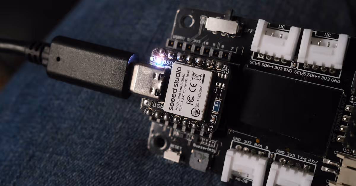
ENG | XAIO-nRF52840 (Seeed Studio) and MicroPython
Few MicroPython code snippets for XIAO-nRF52840 and XIAO Expansion board. LED, display, RTC and buzzer examples.
This somewhat copies article about [nRF52840 Dongle](This was docummented for a dongle
Download and flash MicroPython firmware
Note that board has preloaded firmware for Sense version.
1
2
3
4
5
6
[pavel@marten -=- ~]$ cd Downloads
[pavel@marten -=- ~/Downloads]$ wget https://micropython.org/resources/firmware/SEEED_XIAO_NRF52-20250415-v1.25.0.uf2
Saving 'SEEED_XIAO_NRF52-20250415-v1.25.0.uf2'
HTTP response 200  [https://micropython.org/resources/firmware/SEEED_XIAO_NRF52-20250415-v1.25.0.uf2]
SEEED_XIAO_NRF52-202 100% [==============================================================================================================>]  511.00K    --.-KB/s
                          [Files: 1  Bytes: 511.00K [805.99KB/s] Redirects: 0  Todo: 0  Errors: 0
Now press reset button twice to enter bootloader mode and upload firmware
1
[pavel@marten -=- ~/Downloads]$ cp ~/Downloads/SEEED_XIAO_NRF52-20250415-v1.25.0.uf2 /run/media/pavel/XIAO-SENSE
On Linux, drive is not always automatically mounted - I guess it’s handled by KDE Plasma. To mount it, try the following:
Command above has
/dev/sda. This is correct for NRF52 development board, for Raspberry Pi Pico and clones, it’s/dev/sda1.
Side note: Upload via serial
It is possible to upload application or update firmware via serial port. Later it was found that it behaves as both mass storage and serial port, which can exposed by lsusb -v or printing last kernel messages sudo journalctl -k -n 50
1
2
3
4
5
6
7
8
9
10
11
12
13
14
15
16
17
18
19
Dec 07 22:26:09 thinkpad kernel: usb 1-2: new full-speed USB device number 47 using xhci_hcd
Dec 07 22:26:09 thinkpad kernel: usb 1-2: New USB device found, idVendor=2886, idProduct=0045, bcdDevice= 1.00
Dec 07 22:26:09 thinkpad kernel: usb 1-2: New USB device strings: Mfr=1, Product=2, SerialNumber=3
Dec 07 22:26:09 thinkpad kernel: usb 1-2: Product: XIAO nRF52840 Sense
Dec 07 22:26:09 thinkpad kernel: usb 1-2: Manufacturer: Seeed
Dec 07 22:26:09 thinkpad kernel: usb 1-2: SerialNumber: E0646F46E3EBE14A
Dec 07 22:26:09 thinkpad kernel: cdc_acm 1-2:1.0: ttyACM0: USB ACM device
Dec 07 22:26:09 thinkpad kernel: usb-storage 1-2:1.2: USB Mass Storage device detected
Dec 07 22:26:09 thinkpad kernel: scsi host1: usb-storage 1-2:1.2
Dec 07 22:26:10 thinkpad kernel: scsi host1: scsi scan: INQUIRY result too short (5), using 36
Dec 07 22:26:10 thinkpad kernel: scsi 1:0:0:0: Direct-Access     Adafruit nRF UF2          1.0  PQ: 0 ANSI: 2
Dec 07 22:26:10 thinkpad kernel: sd 1:0:0:0: Attached scsi generic sg1 type 0
Dec 07 22:26:10 thinkpad kernel: sd 1:0:0:0: [sdb] 65801 512-byte logical blocks: (33.7 MB/32.1 MiB)
Dec 07 22:26:10 thinkpad kernel: sd 1:0:0:0: [sdb] Write Protect is off
Dec 07 22:26:10 thinkpad kernel: sd 1:0:0:0: [sdb] Mode Sense: 03 00 00 00
Dec 07 22:26:10 thinkpad kernel: sd 1:0:0:0: [sdb] No Caching mode page found
Dec 07 22:26:10 thinkpad kernel: sd 1:0:0:0: [sdb] Assuming drive cache: write through
Dec 07 22:26:11 thinkpad kernel:  sdb:
Dec 07 22:26:11 thinkpad kernel: sd 1:0:0:0: [sdb] Attached SCSI removable disk
Bootloader is described on Adafruit page
Note that the following example is valid for applications. Updating firmware is different and maybe bootloader itself is protected.
Also note that tool is not compatible with nRF Dongle and vice versa. They have completely different bootloader.
1
2
3
4
5
6
# Install Python tool
pip3 install adafruit-nrfutil
# Generate package from hex file
adafruit-nrfutil dfu genpkg --dev-type 0x0052 --application blinky.hex dfu-package.zip
# Upload while XIAO is in boot mode
adafruit-nrfutil dfu serial --package dfu-package.zip -p /dev/ttyACM0
Test basics
1
2
3
4
5
6
7
8
9
10
11
12
13
14
15
16
17
18
19
20
21
22
23
24
25
26
27
28
29
30
31
32
33
34
35
36
37
38
39
40
41
42
43
44
45
[pavel@marten -=- /home/pavel/Downloads]$ mpremote a1
Connected to MicroPython at /dev/ttyACM1
Use Ctrl-] or Ctrl-x to exit this shell
MicroPython v1.25.0 on 2025-04-15; XIAO nRF52840 Sense with NRF52840
Type "help()" for more information.
>>> help()
Welcome to MicroPython!

For online docs please visit http://docs.micropython.org/

Quick overview of commands for the board:
  board.LED(n)    -- create an LED object for LED n (n=1,2,3,4)

If compiled with SD=<softdevice> the additional commands are
available:
  ble.enable()    -- enable bluetooth stack
  ble.disable()   -- disable bluetooth stack
  ble.enabled()   -- check whether bluetooth stack is enabled
  ble.address()   -- return device address as text string

Control commands:
  CTRL-A        -- on a blank line, enter raw REPL mode
  CTRL-B        -- on a blank line, enter normal REPL mode
  CTRL-D        -- on a blank line, do a soft reset of the board
  CTRL-E        -- on a blank line, enter paste mode

For further help on a specific object, type help(obj)
>>> import board
>>> l1=board.LED(1)
>>> l1.on()
>>> l1.off()
>>> l1.on()
>>> l2=board.LED(2)
>>> l2.on()
>>> l3=board.LED(3)
>>> l3.on()
>>> board.LED(4).on()
>>> import sys
>>> sys.platform
'nrf52'
>>> sys.implementation
(name='micropython', version=(1, 25, 0, ''), _machine='XIAO nRF52840 Sense with NRF52840', _mpy=7942, _build='SEEED_XIAO_NRF52')
>>> import time
>>> time.ticks_ms()
306696
| LED | Note |
|---|---|
| 1 | Tiny green |
| 2 | Red |
| 3 | Green |
| 4 | Blue |
When you have XIAO Expansion Board, you may try I2C scan:
1
2
3
4
>>> from machine import Pin, I2C
>>> i2c_0 = I2C(0, sda=Pin(4), scl=Pin(5))
>>> i2c_0.scan()
[60, 81]
| 8bit address | 7bit address | Device |
|---|---|---|
| 0x78 (120) | 0x3c (60) | 128x64 0.96” OLED (ZJY-2864KSWPG01) with SSD1306 controller |
| 0xA2 (162) | 0x51 (81) | RTC PCF8563T |
MicroPython uses 7bit address, while documentation usually mentions 8bit address (or pair), lowest bits is zero for write and one for read operation.
Test RTC
1
2
3
>>> data = i2c_0.readfrom_mem(81, 0x02, 7)
>>> data
b'\xa6\x88\x80\x8c\xa0\xa7p'
Hmm. We got something.
Test BLE functionality
1
2
3
4
>>> import bluetooth
Traceback (most recent call last):
  File "<stdin>", line 1, in <module>
ImportError: no module named 'bluetooth'
Actually it has very weird BLE module with no useable functions.
1
2
3
4
5
6
7
8
9
10
11
12
13
14
15
16
>>> import ble
>>> help(ble)
object <module 'ble'> is of type module
  __name__ -- ble
  enable -- <function>
  disable -- <function>
  enabled -- <function>
  address -- <function>
>>> print(dir(ble))
['__class__', '__name__', '__dict__', 'address', 'disable', 'enable', 'enabled']
>>> ble.enable()
SoftDevice enabled
>>> ble.address()
'fb:58:6b:52:8b:b7'
>>> ble.enabled()
1
Then, there is weird ubluepy module with basically no documentation. There are like three examples on internet. Good luck using it.
1
2
3
4
5
6
7
8
9
10
11
12
13
14
15
16
17
18
19
20
21
22
23
24
25
26
27
28
29
30
>>> import ubluepy
>>> print(dir(ubluepy))
['__class__', '__name__', 'Characteristic', 'DefaultDelegate', 'Peripheral', 'ScanEntry', 'Scanner', 'Service', 'UUID', '__dict__', 'constants']
>>> help(ubluepy)
object <module 'ubluepy'> is of type module
  __name__ -- ubluepy
  Peripheral -- <class 'Peripheral'>
  Scanner -- <class 'Scanner'>
  ScanEntry -- <class 'ScanEntry'>
  DefaultDelegate -- <class 'DefaultDelegate'>
  UUID -- <class 'UUID'>
  Service -- <class 'Service'>
  Characteristic -- <class 'Characteristic'>
  constants -- <class 'constants'>
>>> help(ubluepy.Scanner)
object <class 'Scanner'> is of type type
  scan -- <function>
>>> help(ubluepy.Peripheral)
object <class 'Peripheral'> is of type type
  withDelegate -- <function>
  setNotificationHandler -- <function>
  setConnectionHandler -- <function>
  getServices -- <function>
  connect -- <function>
  advertise -- <function>
  advertise_stop -- <function>
  disconnect -- <function>
  addService -- <function>
>>> help(ubluepy.Peripheral.advertise)
object <function> is of type function
But I found two files on github that are somewhat relevant:
1
2
3
4
5
>>> import ubluepy
>>> p = ubluepy.Peripheral()
>>> p.advertise(device_name="BleTest")
>>> # Beyond this, good luck and have fun!
>>> # I was not even able to put custom data to the advertisment packet.
Uploading program
This was docummented for a dongle
Now, let’s have fun with expansion board!
Buzzer demo
NOTE: port A3/D3 is actually P0.29
1
2
3
4
5
6
>>> buzzer = PWM(Pin(29))
>>> buzzer
<PWM: Pin=29 freq=0Hz duty=0 invert=0 id=1 channel=0>
>>> buzzer.freq(500)
>>> buzzer.duty_u16(30000)
>>> buzzer.deinit()
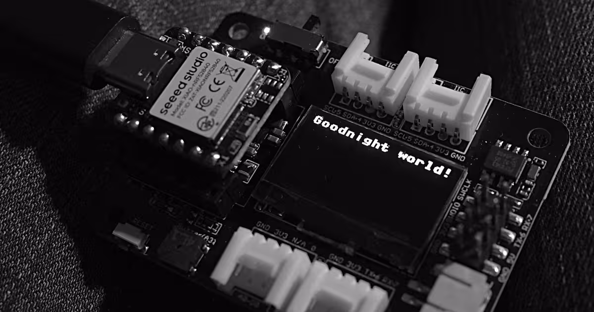
Display demo
See SSD1306 Tutorial, driver is on github.
1
2
3
4
5
6
7
8
9
10
11
12
13
14
15
16
17
18
19
20
21
22
23
24
[pavel@marten -=- /home/pavel/Downloads]$ wget https://raw.githubusercontent.com/micropython/micropython-lib/refs/heads/master/micropython/drivers/display/ssd1306/ssd1306.py
Saving 'ssd1306.py'
HTTP response 200  [https://raw.githubusercontent.com/micropython/micropython-lib/refs/heads/master/micropython/drivers/display/ssd1306/ssd1306.py]
ssd1306.py           100% [====================================================================>]    1.51K    --.-KB/s
                          [Files: 1  Bytes: 1.51K [5.15KB/s] Redirects: 0  Todo: 0  Errors: 0   ]

[pavel@marten -=- /home/pavel/Downloads]$ ls -la ssd1306.py
-rw-r--r--. 1 pavel pavel 4922 Jun  8 21:35 ssd1306.py
[pavel@marten -=- /home/pavel/Downloads]$ mpremote a1 fs cp ssd1306.py :

cp ssd1306.py :
[pavel@marten -=- /home/pavel/Downloads]$ mpremote a1
Connected to MicroPython at /dev/ttyACM1
Use Ctrl-] or Ctrl-x to exit this shell
>>> from machine import Pin, I2C
>>> import ssd1306
>>> i2c = I2C(0, sda=Pin(4), scl=Pin(5))
>>> oled = ssd1306.SSD1306_I2C(128, 64, i2c, addr=0x3C)
>>> oled.fill(1)
>>> oled.show()
>>> oled.fill(0)
>>> oled.show()
>>> oled.text("Goodnight world!", 0,0)
>>> oled.show()
This should
- Download display driver
wget ... - Upload it to development board
mpremote a1 fs cp ssd1306.py :wherea1is alias forconnect /dev/ttyACM1 - Run serial console
- fill screen with white
- update screen (screen is lit now)
- … the rest is quite obvious
RTC demo
RTC requires CR1220 3V battery.
Create helper (this command creates file rtc_pcf8563.py)
1
2
3
4
5
6
7
8
9
10
11
12
13
14
15
16
17
18
19
20
21
22
23
24
25
26
27
28
29
30
31
32
33
34
35
36
37
38
39
40
cat > rtc_pcf8563.py << EOF
# rtc_pcf8563.py
from machine import I2C

__all__ = ['read_rtc', 'set_rtc', 'init_rtc']

def _bcd_to_dec(bcd):
    return (bcd >> 4) * 10 + (bcd & 0x0f)

def _dec_to_bcd(dec):
    return ((dec // 10) << 4) + (dec % 10)

def init_rtc(i2c_bus, address=0x51):
    global _i2c, _addr
    _i2c = i2c_bus
    _addr = address

def read_rtc():
    data = _i2c.readfrom_mem(_addr, 0x02, 7)
    seconds = _bcd_to_dec(data[0] & 0x7f)
    minutes = _bcd_to_dec(data[1] & 0x7f)
    hours = _bcd_to_dec(data[2] & 0x3f)
    day = _bcd_to_dec(data[3] & 0x3f)
    weekday = data[4] & 0x07
    month = _bcd_to_dec(data[5] & 0x1f)
    year = _bcd_to_dec(data[6]) + 2000
    return (year, month, day, hours, minutes, seconds, weekday)

def set_rtc(year, month, day, hours, minutes, seconds, weekday=0):
    data = bytearray([
        _dec_to_bcd(seconds),
        _dec_to_bcd(minutes),
        _dec_to_bcd(hours),
        _dec_to_bcd(day),
        weekday,
        _dec_to_bcd(month),
        _dec_to_bcd(year - 2000)
    ])
    _i2c.writeto_mem(_addr, 0x02, data)
EOF
Copy it to device
1
mpremote a1 fs cp rtc_pcf8563.py :
Play with it
1
2
3
4
5
6
7
8
9
Connected to MicroPython at /dev/ttyACM1
Use Ctrl-] or Ctrl-x to exit this shell
>>> from machine import Pin, I2C
>>> import rtc_pcf8563
>>> i2c = I2C(0, sda=Pin(4), scl=Pin(5))
>>> rtc_pcf8563.init_rtc(i2c)
>>> rtc_pcf8563.read_rtc()
(2025, 6, 8, 15, 5, 35, 0)
>>> rtc_pcf8563.set_rtc(2025, 6, 8, 14, 30, 0, 0)
NOTES:
- Weekday 0 is sunday
- Time was set previously
- RTC needs CR1220 battery (D=12mm, h=2.0mm) to keep time without USB power.
Conclusion
This device is very nice and I’m happy I bough expansion board.
What I found problematic is ubluepy module which is dead, undocumented and almost impossible to find (try “import ubluepy” filetype:py in google or similar), but similar bluepy exists, so maybe with some guesses and effort it’s possible to use it, but my hopes are low.
I found two blog posts:
- https://madflex.de/seeed-xiao-ble-nrf52840-with-micropython/
- https://madflex.de/micropython-and-bluetooth-on-nRF/
with the very same conclusion.
However, for MicroPython, I’d recommend sticking with Raspberry Pi Pico family, which is very cheap, well documented, well supported, and with large user community. I haven’t tested ESP32 thou. But I’m afraid that combination of nRF52840 and MicroPython does not make sense, as boards are more expensive and selling point is BLE and/or low-power applications. For use with expansion board, XIAO Seeed RP2040 will work as well. This does not mean board is useless, as it can be programmed in C+Zephyr RTOS, where BLE works and MicroPython is still good for fast checks if other stuff works.
Links
- XIAO nRF52840 wiki
- XIAO nRF52840 MicroPython
- XIAO Expansion Board Wiki
- XIAO nRF52840 Schema
- TLV733P voltage regulator (U6 in schema)
- NOTE: TLV733xx is series, it does not mean 3.3V output voltage for specified 1.4 input voltage. Sadly it needs higher input voltage. When 2.6V from 2xNiMH batteries is applied to input, output voltage is roughly 2.35V. Chip and SSD1306 OLED display work. Voltage regulator has 0.125V drop at 300mA and Vout=3.3V.
- BQ25101 battery charging circuit
- Charging characteristics of XIAO_nRF52840 and XIAO_ESP32C3
TODO: test SPI flash
Notes
Expansion board has charging current set by 2K resistors connected to ISET pins of ETA6003 chip to 1V/2KΩ=500mA, whereas XIAO nRF82840 has charging current either 50mA (P0.13 high) or 100mA (P0.13 low) so it can use smaller capacity batteries.