ENG | Raspberry Pi Pico, MicroPython, and Nokia 5110 display
Learn how to connect and use the Nokia 5110 LCD display with a Raspberry Pi Pico using MicroPython. Tutorial covers the wiring, code implementation, and troubleshooting tips.
Introduction
The Nokia 5110 LCD (PCD8544) is a compact and affordable monochrome display with 84x44 pixels resolution that has become a popular choice for hobbyists and makers working with microcontrollers like the Raspberry Pi Pico. Despite its simple design, the Nokia 5110 offers a convenient way to display text, graphics, and basic animations, making it suitable for a wide range of projects, from status displays and user interfaces to games (snake!).
In this tutorial, we’ll explore how to connect the Nokia 5110 display to the Raspberry Pi Pico using MicroPython, which was introduced in the previous article. We’ll walk through the necessary wiring, explain the code implementation, and provide some helpful tips for troubleshooting and customization.
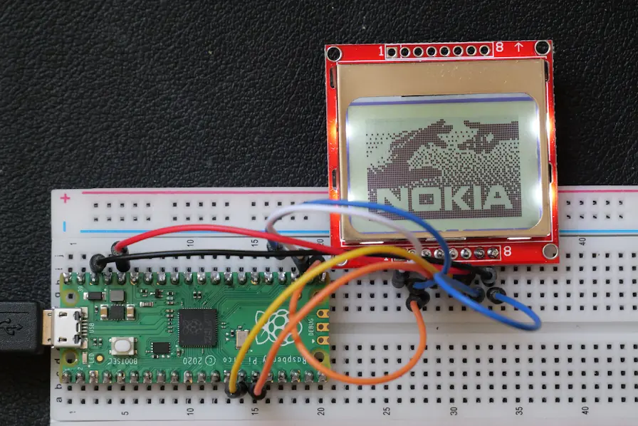
Wiring
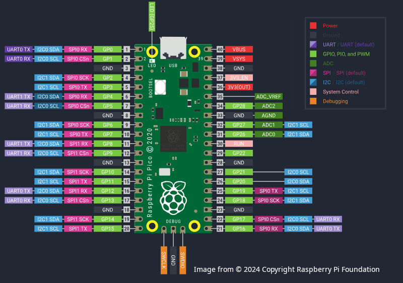
| LCD Pin | Name | Note | Pico Pin | Name |
|---|---|---|---|---|
| 1 | RST | External reset input, active low | 22 | GP17 |
| 2 | CE | Chip enable, active low | 24 | GP18 |
| 3 | D/C | Data high / Command low | 21 | GP16 |
| 4 | DIN | Serial data input | 15 | GP11 SPI:MOSI/TX |
| 5 | CLK | Serial clock, up to 4MHz | 14 | GP10 SPI:SCK |
| 6 | VCC | Supply voltage 2.7-3.3V | 36 | 3V3 |
| 7 | BL | Backlight, active low | ?? | Depends |
| 8 | GND | Ground | 38 | GND |
Backlight is on when BL is connected to ground, so it does not have to be connected to Pico.
Code (adopted from example)
As I understand it numbers in SPI(1, baudrate=1000000, mosi=Pin(11), sck=Pin(10)) and SPI wiring must match Raspberry Pi Pico pinout. There are two SPI drivers that can select from certain combinations of pins.
Wiring is according to YouTube video tutorial, which uses CircuitPython from AdaFruit, and it’s mostly demonstration without much practical information. The following code uses MicroPython.
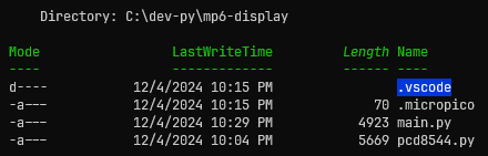
I used micropython-pcd8544 repository, copied example from README.md file into my main.py file as a starting point. We need to download pcd8544.py from the repository and to put it next to our main.py file into project folder and initialized project using MicroPico extension. Then upload it to Pico. That’s all.
Project directory then looks like this:
Changes from the original example are pins, delays
1
2
3
4
5
6
7
8
9
10
11
12
13
14
15
16
17
18
19
20
21
22
23
24
25
26
27
28
29
30
31
32
33
34
35
36
37
38
39
40
41
42
43
44
45
46
47
48
49
50
51
52
53
54
55
56
57
58
59
60
61
62
63
64
65
66
67
68
69
70
71
72
73
74
75
76
77
78
79
80
81
82
83
84
85
86
87
88
89
90
91
92
93
94
95
96
97
98
99
100
101
102
103
104
import pcd8544
from machine import Pin, SPI
import sys
from utime import sleep

"""
Philips PCD8544 / Nokia 5110 LCD pinout according to backside description and
this video tutorial https://educ8s.tv/raspberry-pi-pico-nokia5110-display-tutorial-using-circuitpython/,
https://github.com/educ8s/CircuitPython_PCD8544_Graphics
sadly, this is for CircuitPython and AdaFruit ecosystem

Library used: https://github.com/mcauser/micropython-pcd8544

This code is based on example.

|  Pin | Name | Note                             | Pico Pin             |
| ---: | ---- | -------------------------------- | -------------------- |
|    1 | RST  | External reset input, active low | 22: GP17             |
|    2 | CE   | Chip enable, active low          | 24: GP18             |
|    3 | D/C  | Data high / Command low          | 21: GP16             |
|    4 | DIN  | Serial data input                | 15: GP11 SPI:MOSI/TX |
|    5 | CLK  | Serial clock, up to 4MHz         | 14: GP10 SPI:SCK     |
|    6 | VCC  | Supply voltage 2.7-3.3V          | 36: 3V3              |
|    7 | BL   | Backlight, active low            | Depends              |
|    8 | GND  | Ground                           | 38: GND              |
"""

spi = SPI(1, baudrate=1000000, mosi=Pin(11), sck=Pin(10))
cs  = Pin(18)
dc  = Pin(16)
rst = Pin(17)

lcd = pcd8544.PCD8544(spi, cs, dc, rst)

# test pattern (50% on)
lcd.data(bytearray([0x55, 0xAA] * 42 * 6))
sleep(1)

# bitmap smiley (horzontal msb)
lcd.clear()
# draw 8x16 in bank 0 (rows 0..7)
lcd.position(0, 0)
lcd.data(bytearray(b'\xE0\x38\xE4\x22\xA2\xE1\xE1\x61\xE1\x21\xA2\xE2\xE4\x38\xE0\x00'))

sleep(1)
# draw 8x16 in bank 1 (rows 8..15)
lcd.position(0, 1)
lcd.data(bytearray(b'\x03\x0C\x10\x21\x21\x41\x48\x48\x48\x49\x25\x21\x10\x0C\x03\x00'))
sleep(1)

# toggle display, image persists in DDRAM
lcd.power_off()
lcd.power_on()
sleep(1)

# nokia logo bitmap (84x48/8=504 bytes)
lcd.clear()
lcd.data(bytearray( \
    b'\x80\x00\x00\x80\x00\x00\x80\x00\x00\x80\x00\x00\x80\x00\x00\x80\x00\x00\x80\x80\x40\x40\x40\x80\x80' \
    b'\xC0\xC0\x40\xC0\xA0\xE0\xC0\xE0\xE0\xF0\xF0\xF8\xF8\xF8\xFC\xFC\xFE\xEE\xF4\xF0\xF0\x70\x30\x00\x80' \
    b'\x00\x00\x80\x00\x0C\x9C\x1C\x38\xB8\x38\x38\xB8\xF8\xF0\xF0\xF0\xF0\xF0\xF0\xF0\xF0\xF0\xF0\xF0\xF0' \
    b'\xF0\xF0\xF0\xF0\xF0\xF8\xF8\xF8\xF8\x88\x20\x8A\x20\x08\x22\x08\x00\x0A\x00\x00\x02\x80\x71\xBA\xDA' \
    b'\xFD\xDD\xED\xDE\xEE\xF7\xFF\xFB\xFD\xFD\xFE\xFF\x7F\x3F\x1F\x9F\x3F\x7F\x6F\x0F\xAF\x1F\xBF\x3E\x3C' \
    b'\x7A\x78\x70\x22\x88\xA0\x2A\x80\x08\x62\xE0\xE0\xF2\xF0\x58\xDA\xF8\xFC\x92\xFE\xFF\xFF\xD3\xFF\xFD' \
    b'\xF3\xE1\xF0\xF9\x7F\xBF\x3F\x8F\x2F\x4F\xAF\x0F\x4F\xA7\x0F\xAF\x87\x2F\x82\x80\x20\xC0\x80\x80\x50' \
    b'\x40\xC4\xD0\xA0\xE8\xE4\xEA\xFF\xFB\xFD\xFF\xFF\xFF\xFF\xFF\xEF\x4F\x27\x53\xA8\x54\x29\x4A\xB5\x82' \
    b'\xAC\xA1\x8A\xB6\x50\x4D\x32\xA4\x4A\xB4\xA9\x4A\x52\xB4\xAA\x45\xA8\xDA\x22\xAC\xD2\x2A\x52\xA8\x52' \
    b'\x4C\xB0\xAD\x43\x5B\xB3\x45\xA8\x5B\xA3\xAB\x55\xA8\x52\x54\xA9\x56\xA8\x45\xBA\xA4\x49\x5A\xA2\x54' \
    b'\xAA\x52\xFE\xFF\xFF\xFE\xFD\xFF\xFF\xFF\xFE\xFF\xFF\xFF\xFF\xFF\xFF\xFF\xFF\xFF\xFF\xFF\xFF\x7F\xFF' \
    b'\xFE\xBF\x7F\xBF\xBF\xFF\xDF\xBF\x5F\xDF\x7F\xDF\x7F\xDF\xAF\x7F\xEE\x8E\xF1\x6E\x99\xF7\x6A\xDD\xB2' \
    b'\x6E\xD5\x7A\xD7\xAC\x75\xDB\x6D\xD5\x7A\xD7\xAC\x7B\xE5\xDE\xA9\x77\xDA\xB5\xEE\x59\xB6\xEB\xDD\xB6' \
    b'\x69\xD6\xBF\xE8\x55\xEF\xB9\xD6\xED\xB5\x5B\xAB\xFF\xFD\xF7\xFF\x01\x01\x01\x01\xE1\xC1\x81\x03\x05' \
    b'\x0F\x1D\x2F\x7E\x01\x00\x01\x01\xFF\xFE\x03\x01\x01\x00\xF1\xF0\xF1\x71\xF1\xF1\xB1\xF1\x01\x01\x01' \
    b'\x03\xFE\xFF\x01\x01\x01\x01\xBE\x1B\x0D\x07\x03\x41\xE1\xF1\xF9\x6D\xFF\xFF\x00\x01\x01\x01\xFF\xFF' \
    b'\xEB\x3E\x0D\x03\x01\x41\x71\x70\x41\x01\x03\x0E\x3B\xEF\xFE\xFB\xEE\x7D\xF7\xFF\xFF\xFF\xFF\xFE\xFF' \
    b'\xF0\xF0\xF0\xF0\xFF\xFF\xFF\xFF\xFE\xFC\xF8\xF0\xF0\xF0\xF0\xF0\xF0\xFF\xFF\xF8\xF0\xF0\xF0\xF1\xF1' \
    b'\xF1\xF1\xF1\xF1\xF1\xF1\xF0\xF0\xF0\xF8\xFF\xFF\xF0\xF0\xF0\xF0\xFF\xFF\xFE\xFC\xF8\xF0\xF0\xF1\xF3' \
    b'\xF7\xFF\xFF\xF0\xF0\xF0\xF0\xFF\xF3\xF0\xF0\xF0\xFC\xFC\xFC\xFC\xFC\xFC\xFC\xFC\xF0\xF0\xF0\xF3\xFF' \
    b'\xFF\xFF\xFF\xFF'))
sleep(1)

lcd.invert(True)
sleep(1)
lcd.invert(False)
sleep(1)

#lcd.reset()
#lcd.init()

# swtich to vertical addressing
#lcd.init(horizontal=False)

# adjust contrast, bias and temp
lcd.contrast(0x1f, pcd8544.BIAS_1_40, pcd8544.TEMP_COEFF_0)
sleep(1)
lcd.contrast(0x3f, pcd8544.BIAS_1_48, pcd8544.TEMP_COEFF_0)
sleep(1)
lcd.contrast(0x3c, pcd8544.BIAS_1_40, pcd8544.TEMP_COEFF_0)
sleep(1)
lcd.contrast(0x42, pcd8544.BIAS_1_48, pcd8544.TEMP_COEFF_0)
sleep(1)
lcd.contrast(0x3f, pcd8544.BIAS_1_40, pcd8544.TEMP_COEFF_2)
sleep(1)
print("Done")
Troubleshooting
- Sadly, one of my two displays did not work and briefly blinked when powered on ☠
- It’s a bit sensitive to timing? errors during data transfer, sometimes nothing is drawn, sometimes Nokia logo is distorted
- I dropped breadboard with display long time after writing this article and it fell apart. What surprised me that display consists of several parts: display with a rubber! connector at the top part without visible contacts that is pressed against board by a metal frame and secured by four metal clips. So possible cause of not working display or various flaws could be loose mechanical fit or slight misalignment between connector and circuit board. I was able to put it back and use display for some time without issues.
Deciphering Frambuffer Layout
Working with the frame buffer of a Nokia display can be both fun and challenging, especially when encoding or decoding bit patterns. Here’s how it works:
Coordinate System and Addressing Mode:
- In horizontal addressing mode, you set the cursor position using X and Y coordinates.
- The X-coordinate ranges from 0 to 83 (for 84 pixels across), and the Y-coordinate ranges from 0 to 5, representing 6 rows of 8-pixel-high blocks (for 48 vertical pixels total).
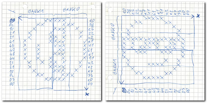
Frame Buffer Layout
- Each byte in the frame buffer represents a vertical column of 8 pixels within a row. The least significant bit (LSB) corresponds to the top pixel, and the most significant bit (MSB) corresponds to the bottom pixel.
- For example, a byte with the value 0xE0 (0b11100000) means that the top three pixels in the column are on (black), and the rest are off (white). Specifically, in the first row (Y=0), this would correspond to pixels at positions:
- (0,7) (LSB, topmost pixel),
- (0,6),
- (0,5). Let’s decode the fragment of smiley code above
1
2
3
4
5
6
7
8
# bitmap smiley (horzontal msb)
lcd.clear()
# draw 8x16 in bank 0 (rows 0..7)
lcd.position(0, 0)
lcd.data(bytearray(b'\xE0\x38\xE4\x22\xA2\xE1\xE1\x61\xE1\x21\xA2\xE2\xE4\x38\xE0\x00'))
# draw 8x16 in bank 1 (rows 8..15)
lcd.position(0, 1)
lcd.data(bytearray(b'\x03\x0C\x10\x21\x21\x41\x48\x48\x48\x49\x25\x21\x10\x0C\x03\x00'))
Practical Applications:
- This layout makes it relatively straightforward to display text. With just 6 rows and variable-width fonts, you can easily write multiple lines of text or graphics.
- However, imagining or visualizing the mapping of bits to pixels can be tricky. Tools or visual aids can be incredibly helpful when designing patterns, such as converting a smiley face into a bitmask.
Understanding the bit-level representation of the frame buffer is crucial for rendering graphics and text efficiently on Nokia displays. Although the mapping might seem unintuitive at first, it’s optimized for minimal memory usage (only 504 bytes for the entire display) and straightforward updates to individual rows or columns.
Displaying text
This is minimal, hopefully self-explanatory example of displaying text. In first loop it goes through rows and positions cursor, in the second loop it goes through characters of text and sends six bytes from font table to display.
Harder part is getting and/or preparing font file, but I guess it’s a topic for the future article.
1
2
3
4
5
6
7
8
9
10
11
12
13
14
15
16
17
18
19
20
21
22
23
24
25
26
27
28
29
import pcd8544
from machine import Pin, SPI
import sys
from utime import sleep_ms
# Load font file
font_8x6 = bytearray(6*256)
with open("/font-6x8.bin", "rb") as file:
  n_read = file.readinto(font_8x6)
  assert(n_read == 6*256)
# Initialize SPI display
spi = SPI(1, baudrate=1000000, mosi=Pin(11), sck=Pin(10))
lcd = pcd8544.PCD8544(spi, cs = Pin(18), dc = Pin(16), rst = Pin(17))
lcd.clear()
sleep_ms(200)
# Display text
for row, text in enumerate([
    "\x10Hello world!\x02",
    "ABCDEFGHIJKLMNOPQRSTUVWXYZ",
    "abcdefghijklmn",
    "opqrstuvwxyz",
    "\xDB\xDB\xDB\xB2\xB1\xB0\xB0\x10",
    "The last row .>"]):
  lcd.position(0, row)
  for ch in text:
    start_index = ord(ch)*6
    glyph = font_8x6[start_index:start_index+6]
    lcd.data(glyph)
    sleep_ms(20)
print("DONE.")
In C/Zephyr code may look like this:
1
2
3
4
5
6
7
8
9
10
11
12
13
14
15
16
17
void fb_write(int row, int x, const char *text) {
    int dst_index = row * DISPLAY_WIDTH + x;
    while (*text) {
        uint16_t ch = (uint8_t)(*text);
        int src_index = ch * 6;
        for (int i = 0; i < 6; i++) {
            if (dst_index >= DISPLAY_FB_SIZE)
                return;
            framebuffer[dst_index++] = font_data[src_index + i];
        }
        text++;
    }
}

memset(framebuffer, 0, DISPLAY_FB_SIZE);
fb_write(1,0, "Hello world!");
display_write(display, 0, 0, &display_descriptor, framebuffer);
As of 2025-07-14 Zephyr does not have driver for this display, but framebuffer layout is the very same when using solomon_ssd1306fb OLED display and likely many others.
Bm437 HP 100LX Font file can be downloaded font-6x8.bin, but be careful about licence.
Addendum (2025-10-17)
Easier way of displaying text using built-in 8x8 font is something like
1
2
3
4
5
6
7
8
from framebuf import FrameBuffer, MONO_VLSB
width=84
height=48
buffer=bytearray(width*height//8)
fb = FrameBuffer(buffer, width, height, MONO_VLSB)
fb.fill(0)
fb.text("Hello world", 0, 0) # str, x, y, [color=1])
# proceed with transfering buffer to display via SPI (or I2C)
Changelog
- 2024-03-18: Initial version
- 2024-12-05: Added framebuffer layout, revised conclusion, added missing puzzle pieces
- 2024-12-09: Added text example
- 2025-07-14: Added Zephyr/C example
- 2025-10-17: Added easy text rendering
Conclusion
This tutorial has shown you how to set up and use the Nokia 5110 display with a Raspberry Pi Pico and MicroPython. By understanding its framebuffer layout and implementing basic text or graphics, you now have the tools to integrate this display into your own projects.
The examples provided are a foundation for further experimentation. You can modify the code to add custom fonts, display dynamic data, or even create simple graphical interfaces. For more complex projects, consider exploring additional peripherals or displays that complement your design goals.
Feel free to adapt these techniques to suit your specific needs, and let this serve as a stepping stone for deeper exploration into microcontrollers and displays.