ENG | Raspberry Pi Pico, MicroPython, and Sitronix ST7567 display
Brief intro to using the Sitronix ST7567 LCD display with a Raspberry Pi Pico and MicroPython. Tutorial covers the wiring, code implementation, and troubleshooting tips.
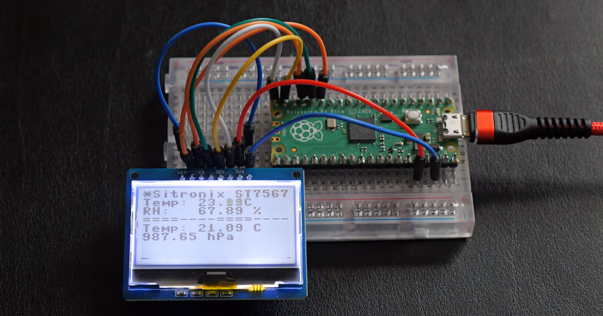
I was not able to buy good old PCD8544 display so I tried to look elsewhere. In one Czech eshop, I found this display which has similar properties, it is perhaps even cheaper, has higher resolution, backlight is brighter. There was slight issue with documentation which does not provide good defaults and MicroPython drivers I found on GitHub had GPL license. I just don’t want to infect my code with it. What I found is that contrast/electronic volume set to zero gives higher contrast, whereas value 0x3f makes whole display black and text is barely readable only at angle.
I guess for next projects TFT/IPS displays might be better option, they provide higher resolution, they are just not good for low power scenarios, but Raspberry Pico is not suitable microcontroller anyways and for most projects, it does not matter. OLED displays such as SSD1306/SSD1315 are super tiny and larger ones are expensive.
This article is basically a repository for self-documenting code and I’ll just link few articles here:
For simplicity demo code uses built-in 8x8 font.
Notes in comments are quite important.
1
2
3
4
5
6
7
8
9
10
11
12
13
14
15
16
17
18
19
20
21
22
23
24
25
26
27
28
29
30
31
32
33
34
35
36
37
38
39
40
41
42
43
44
45
46
47
48
49
50
51
52
53
54
55
56
57
58
59
60
61
62
63
64
65
66
67
68
69
70
71
72
73
74
75
76
77
78
79
80
81
82
83
84
85
86
87
88
89
90
91
92
93
94
95
96
97
98
99
100
101
102
103
104
105
106
107
108
109
110
111
112
113
114
115
116
117
118
119
120
121
122
123
124
125
126
127
128
129
130
131
132
133
134
135
136
137
138
139
140
# SPDX-License-Identifier: MIT
# Copyright (c) 2025 Pavel Perina
#
# MicroPython Sitronix ST7567 128*64 LCD driver
#
# Based on https://www.alldatasheet.com/view.jsp?Searchword=St7567 on some source
# code found on github. Written mostly to avoid GPL licensed code.
# You may need to set electronic volume (contrast) and regulator ratio to drive your
# screen properly.
#
# NOTES:
#
#  * With flipX=True, flipY=False framebuffer start is off by 4 pixels because
#    display memory has 132 columns according to driver datasheet, but display
#    itself has 128 pixels.
#  * One flip is always needed for valid orientation.
#  * Some drivers have staged init issuing several 0x28 commands with 50ms delay.
#  * Display memory has 8 pages, each having 8 lines, each having 8 pixels.
#    so framebuffer is actually 132x512 pixels (64 lines) and allows scrolling by
#    selecting start line.

import time

class ST7567():
    def __init__(self, spi, dc, cs=None, rst=None, contrast=0x00, flipX=False, flipY=True):

        dc.init(dc.OUT, value=0)
        self.dc=dc

        if(cs is not None):
            cs.init(cs.OUT, value = 1)      #disable device port
            self.cs=cs

        if(rst is not None):
            rst.init(rst.OUT, value = 0)    #reset device
            self.rst = rst
            time.sleep_ms(1)
            self.rst.value(1)
            time.sleep_ms(1)

        self.spi=spi

        initCommands=[
            0xE2,                           # Software reset
            0xA2|0x01,                      # LCD bias 0:1/9 1:1/7
            0x81,                           # Electronic volume (contrast) mode
            (contrast&0x3f),                # Contrast value: 0x00-0x3F (default 0x1F - in my experience 0 works best)
            0x20|0x03,                      # Voltage regulator ratio: 0x00-0x07 (3.0-6.5V)
            0x28|0x07,                      # Power control: booster+regulator+follower all on
            0xA0|(0x01 if flipX else 0x00), # Segment direction: 0=normal, 1=reversed (flip X)
            0xC0|(0x08 if flipY else 0x00), # Common output direction: 0=normal, 8=reversed (flip Y)
            0x40|0x00,                      # Display start line: 0x40-0x7F (line 0-63)
            0xAE|0x01,                      # Display on/off, 0=off,1=on
        ]

        self.writeCommands(initCommands)

    # Write command(s)
    def writeCommands(self, cmd):
        self.cs.value(0)    # Enable device
        self.dc.value(0)    # Command mode
        self.spi.write(bytearray(cmd))
        self.dc.value(1)    # Disable device

    # Write framebuffer data
    def writeData(self, data):
        self.cs.value(0)
        self.dc.value(1)    # Display data mode
        self.spi.write(data)
        self.dc.value(1)

    # Show framebuffer
    def show(self, buffer):
        self.writeCommands([0x40|0x00])  # Set start line to 0
        for page in range(8):
            self.writeCommands([
                0xB0 | page,    # Set page address (0-7)
                0x10 | 0x00,    # Set column address high nibble
                0x00 | 0x00,    # Set column address low  nibble
            ])
            # Write pages data (8 rows, 128 columns)
            self.writeData(buffer[(128*page):(128*page+128)])


if __name__ == "__main__":
    """
    Wiring expected in this code
    =================================
    GP11            -> RST (Reset)
    GP12            -> DC  (Data/Command)
    GP13 SPI1 CS    -> CS  (Chip select)
    GP14 SPI1 Clock -> SCK (SPI Clock)
    GP15 SPI1 Master Out, Slave In -> SDI (SPI Data In)

    GND             -> GND, LED
    3V3             -> VCC
    """

    print("Running as a standalone test script")
    from machine import Pin, SPI
    from framebuf import FrameBuffer, MONO_VLSB

    print("SPI init")
    spi = SPI(1,
            baudrate=200_000,
            polarity=1,
            phase=1,
            sck=Pin(14),
            mosi=Pin(15)) # under 20Mhz is OK

    print("LCD init")
    lcd=ST7567(spi,
            dc=Pin(12),  # data/command
            cs=Pin(13),  # chipselect, likely not needed for a single SPI device
            rst=Pin(11)) # reset

    print("Loop")
    buffer=bytearray(128*64//8)
    fb = FrameBuffer(buffer, 128, 64, MONO_VLSB)
    counter = 0
    while True:
        fb.fill(0)
        fb.text("*Sitronix ST7567*",0,0)
        fb.text(f"Temp: 23.{counter%99:02d}C", 0, 8)
        fb.text("RH:   67.89 %", 0, 16)
        fb.text("====----====----",0,24)
        fb.text("Temp: 21.09 C",0,32)
        fb.text("987.65 hPa",0,40)
        # Running line at screen bottom to test refresh rate
        fb.pixel( counter   %128,63,1)
        fb.pixel((counter+1)%128,63,1)
        fb.pixel((counter+2)%128,63,1)
        fb.pixel((counter+3)%128,63,1)
        fb.pixel((counter+4)%128,63,1)
        fb.pixel((counter+5)%128,63,1)
        fb.pixel((counter+6)%128,63,1)
        fb.pixel((counter+7)%128,63,1)

        lcd.show(buffer)
        counter += 1
Changes
- 2025-10-29: update notes section