ENG | Pimoroni 2.8" Display Pack - MicroPython and Zephyr
Notes on the Pimoroni 2.8" IPS display with Raspberry Pi Pico and attempts using Zephyr RTOS.
I have tried several displays already and came to the conclusion that ILI9341 displays have rather unattractive colors. For the weather-station project, another disadvantage is the 20 cm flat cable, which is not very flexible and takes too much space.
I ordered an IPS display and an E-Ink display which are both basically Raspberry Pi Pico shields. E-Ink display is sort of black box, when it comes to documentation, but it has some poorly written code examples.
So back to one from Pimoroni. It’s quite well documented and comes with prebuilt MicroPython and drivers source code. Let’s explore it.
Links
- Product page
- Display driver source code
- MicroPython Examples
- MicroPython with Pimoroni drivers for Pico 2W
- and Pico graphics library
Description
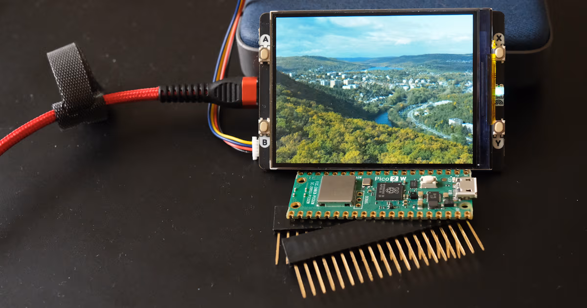
The shield contains not only the display, but also four buttons, an RGB LED controlled by PWM, and a Qwiic/Stemma/LaskaKit connector for sensors. Unfortunately, the pin headers are on the same side as the USB connector and point outward, which complicates the design of a 3D-printed enclosure. And weirdly there are no screw holes, so I guess 3d printed box will require some hot glue.
The display itself has rich, vivid colors—more saturated than those on a Lenovo T480s.
Pinout
| Pin | Description |
|---|---|
| GP6 | SDA |
| GP7 | SCL |
| GP12 | Button-A |
| GP13 | Button-B |
| GP14 | Button-X |
| GP15 | Button-Y |
| GP16 | LCD_DC |
| GP17 | LCD_CS |
| GP18 | LCD_SCLK |
| GP19 | LCD_MOSI |
| GP20 | LCD_BACKLIGHT |
| GP21 | LCD_TE |
| GP 26 | LED_RED |
| GP 27 | LED_GREEN |
| GP 28 | LED_BLUE |
NOTES
- When a button is pressed, the corresponding pin is grounded.
- To turn the LEDs off, use PWM at full duty cycle.
Getting started with MicroPython
The straightforward approach is:
- Download the MicroPython for your variant of Raspberry Pi Pico with drivers for Piromoni boards already included
- Copy it to Raspberry Pico in bootloader mode, for example
1
2
3
$ udisksctl mount -b /dev/sdb1
Mounted /dev/sdb1 at /run/media/pavel/RP2350
$ cp ~/Downloads/rpi_pico2_w-v1.26.1-micropython.uf2 /run/media/pavel/RP2350
- Clone git repository with examples:
1
git clone https://github.com/pimoroni/pimoroni-pico.git
- Go to the display examples:
1
cd pimoroni-pico/micropython/examples/pico_display
- Modify some file(s) for use with 2.8” display and experiment, like
1
2
$ mpremote fs cp pencil.png :
$ mpremote run display_png.py
Some examples are already set up for the 2.8” model, while others require adjusting the pin mapping or display initialization according to comments.
Using file from previous experiments, I modified PNG example to this by removing comments and changing color mode, filename and position:
1
2
3
4
5
6
7
8
9
10
11
12
13
from picographics import PicoGraphics, DISPLAY_PICO_DISPLAY_2, PEN_RGB565
import pngdec
display = PicoGraphics(display=DISPLAY_PICO_DISPLAY_2, pen_type=PEN_RGB565)
display.set_backlight(1.0)
png = pngdec.PNG(display)
try:
    png.open_file("holedna.png")
    png.decode(0, 0, scale=1)
except OSError:
    print("Error: PNG File missing!")
display.update()
while True:
    pass
Zephyr RTOS
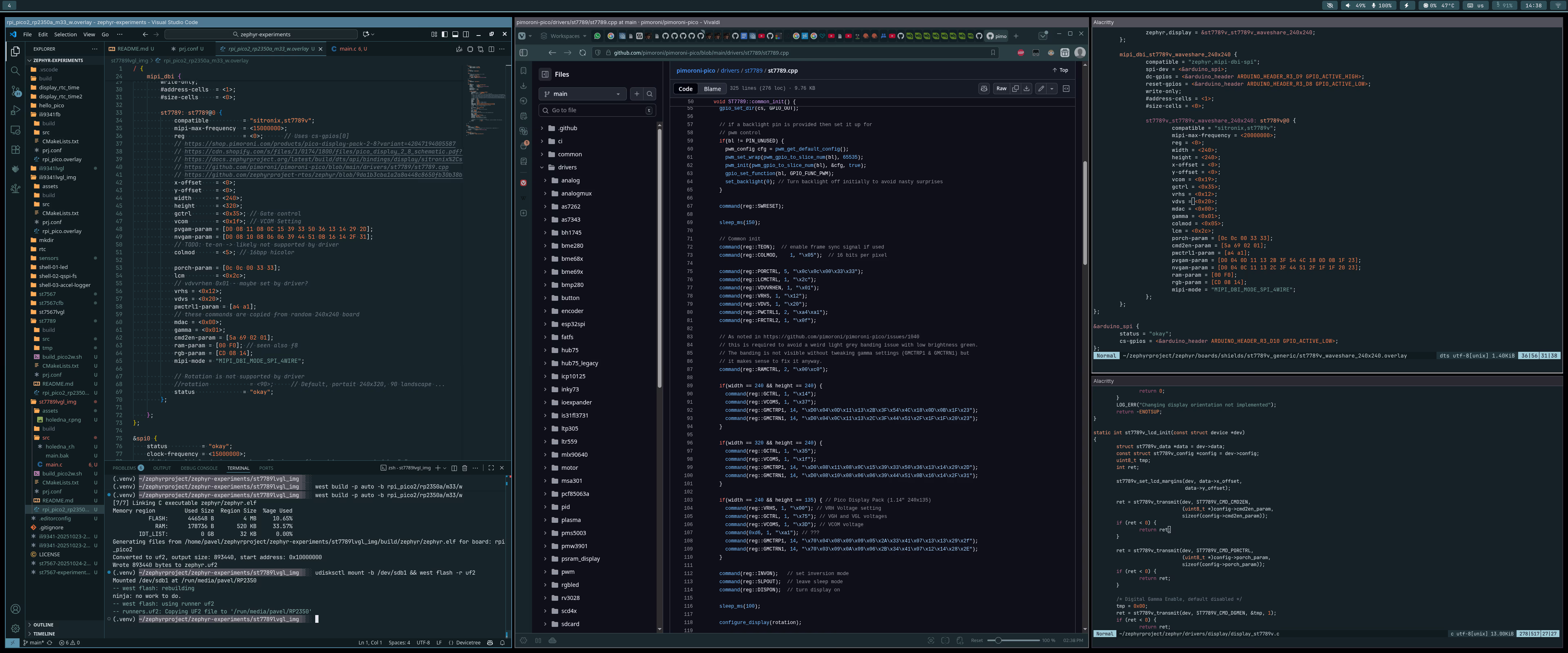
This part of the article focuses on using the Pimoroni 2.8” display (ST7789V controller) with Zephyr RTOS on the Raspberry Pi Pico 2 W. It expands the previous article about using SPI displays in Zephyr RTOS. Basically it’s all about adopting code and writing new device tree.
Expectations
This will be fun, because in device tree definition, there are many initialization parameters required. Hopefully initialization code can be copied from Pimoroni driver linked above and article will be expanded if I find time and will power to do so. Also I have to find out what might be TE pin and if/how reset pin is used.
So far, displays had SPI pins (MOSI, SCK, CS), MIPI-DBI pins (RESET, DC), but this one has TE (tearing effect) instead of reset.
Ok. Let’s try to modify examples from ILI9341 display - this article contains some progressively more complicated code examples.
Reality
I took the framebuffer example from ILI9341 and tried to modify device tree overlay, expecting that the C code can remain unchanged. This would be true, but in the end code needed merging with blinky example to turn on backlight. Nonetheless here is device tree overlay for Raspberry Pi Pico 2 W.
It merges Pimoroni driver with device tree for some 240x240 display shield - Pimoroni driver has different gamma tables and few parameters for 240x240 and 320x240 displays, but there may be differences between IPS and TN displays from various manufacturers. Hard to say.
Sadly, at the time of writing, the ST7789V driver does not support rotation. There were pull requests, but they cannot be merged due to major changes caused by the introduction of the MIPI layer.
 Process of merging code from various sources
Project configuration requires enabling the driver and removing the ILI9341 settings:
1
2
CONFIG_ST7789V=y
CONFIG_ST7789V_BGR565=y
To control the backlight, the source code needs an extra section with GPIO:
1
#include <zephyr/drivers/gpio.h>
1
2
3
4
5
6
7
8
    /* Backlight on */
    const struct gpio_dt_spec backlight_led = GPIO_DT_SPEC_GET(DT_ALIAS(backlight), gpios);
    if (!gpio_is_ready_dt(&backlight_led)) {
        LOG_ERR("LED GPIO not ready.");
        return -1;
    }
    gpio_pin_configure_dt(&backlight_led, GPIO_OUTPUT_ACTIVE);
    gpio_pin_set_dt(&backlight_led, 1);
Sadly, likely the easiest way to get landscape orientation is to patch driver source code by adding a few commands to initialization procedure and then swapping width/height in device tree and test if it works with LVGL.
Building code for Raspberry Pi Pico 2 W is easy (once commands are in shell history)
1
2
3
source ~/zephyrproject/.venv/bin/activate
west build -p auto -b rpi_pico2/rp2350a/m33/w
disksctl mount -b /dev/sdb1 && west flash -r uf2
LVGL image example
This example requires rotating the image by 90° prior to conversion to a header file, enabling CONFIG_LV_USE_ST7789=y in prj.conf, and applying the same changes as in the raw framebuffer example.
Summary
Using this shield in MicroPython is super easy.
Zephyr RTOS is kind of disappointing here. These displays seem very common, but there are no default parameters. Some settings which are not included in driver from Pimoroni are required here and I have no clue what default values should be - they might be excessive. On the other hand, display rotation is not supported.
This was simply an experiment to see whether I could get it working. It took one evening.