ENG | Getting Started with LILYGO T5 Board and MicroPython
Hardware identification, MicroPython flashing with esptool, and testing WiFi connectivity on poorly documented ESP32 board. Experiments with grayscale mode.
So, I finally tried ESP32. On Black Friday I picked up a LILYGO T5 V2.3.1 board with a 2.13” e-ink display and familiar SSD1680 controller.
First Impressions
The documentation is practically non-existent - the typical “Download Arduino IDE, run an example, good luck & have fun!” approach. Fortunately, there’s a schematic on GitHub that reveals what’s actually on the board and with good eye, it’s possible to identify some parts visually. Actually this github repo contains everything - firmware, schematics, arduino examples. Pinout is printed on board.
The board is not exactly small, but no huge either. It’s about twice as wide as Raspberry Pi Pico and maybe two centimeters longer.
It has pinout of uSD card and display and board version printed on PCB, which is great.
Price was about the same, probably lower than my Raspberry Pi Pico 2W, 2.9” inch display in discount and pin header. It might be actually a better option, as it has extra battery charging circuit and it’s compact - although Pico module has buttons and touch screen, this one has a single user button. (Note: week after black Friday, price went up by 30% and it’s likely best to get one from China instead of local resellers).
Due to SD card slot and battery connector, it seems suitable for something like indoor weather station with data logging. But only if it is possible to put SD card into low power mode, which I don’t know - last time I tried it with mosfet. It may not support SDHC/SDXC cards, only small ones.
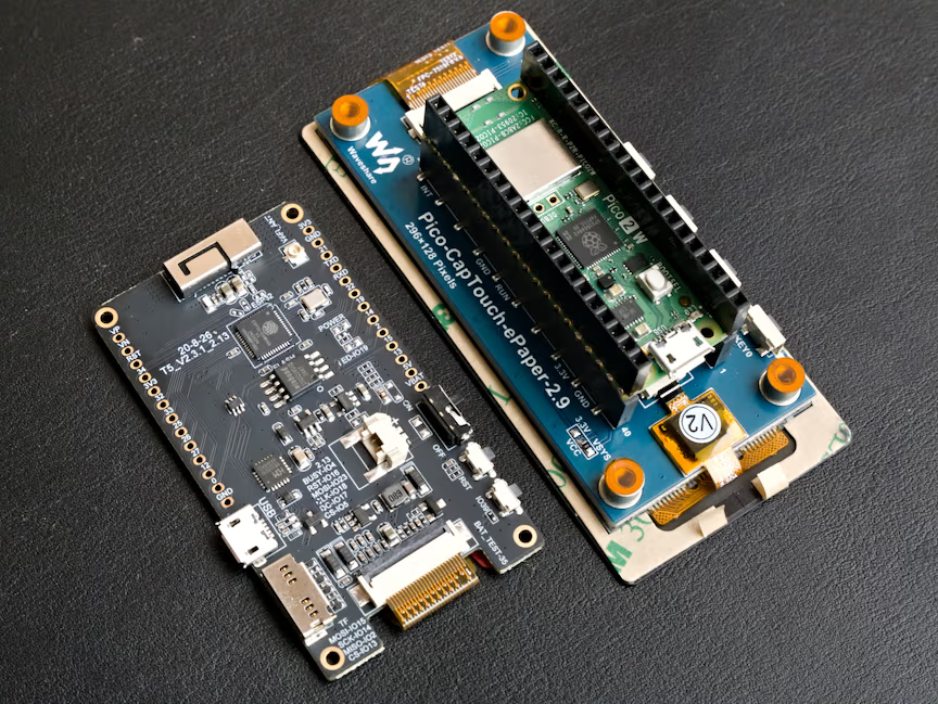 Size comparison of LilyGo T5 V2.3.1 and Waveshare 2.9” Pico Touch
 Size comparison of LilyGo T5 V2.3.1 and Waveshare 2.9” Pico Touch
Hardware breakdown
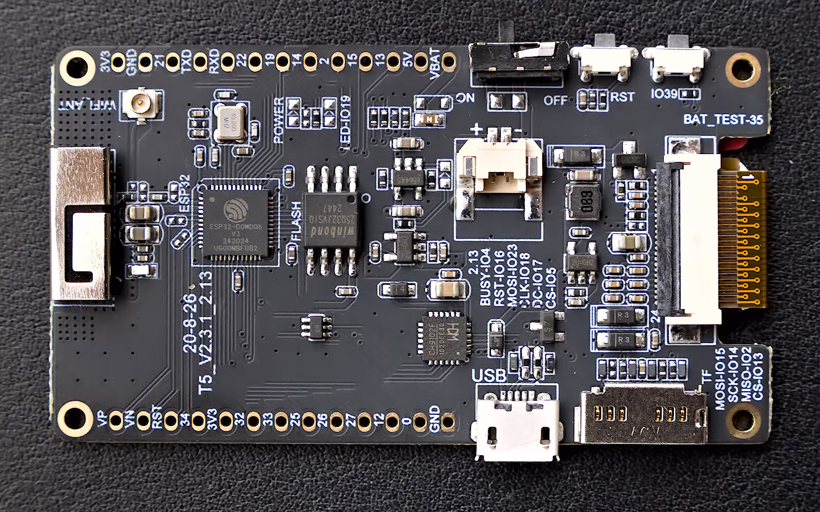 Detailed photo of LilyGo-T5 V2.3.1 ESP32 board
- MCU: ESP32-D0WDQ6-V3
- Dual-core Xtensa LX6 @ 240MHz
- 520 KB internal SRAM
- WiFi 802.11 b/g/n + Bluetooth v4.2/BLE
- Flash: Winbond 25Q32 (4MB Q-SPI flash)
- Display: GDEM0213B74
- 2.13” e-paper display
- 250×122 resolution
- SSD1680 controller
- partial refresh, grayscale (undocumented, no LUTs provided)
- USB-Serial: WDC CH9102F converter
- Crystal: 40 MHz external oscillator
- LiPo Battery Charger: TP4054
- 2K resistor -> 0.36A charging current
R_prog=1000/I_bat*(1.2-4/3*I_bat)
- 2K resistor -> 0.36A charging current
Flashing MicroPython
I went with MicroPython’s ESP32_GENERIC firmware, which supports ESP32-based boards with 4 MB or more flash (including encapsulated WROVER, WROOM which we do not have).
Tools needed:
1
pip install esptool
Flash detection:
When connecting via /dev/ttyACM0 (the CH9102 USB-serial converter), esptool confirms:
1
2
3
Chip type:          ESP32-D0WDQ6-V3 (revision v3.1)
Features:           Wi-Fi, BT, Dual Core + LP Core, 240MHz
Crystal frequency:  40MHz
Flashing commands:
1
2
3
4
5
# Erase existing flash
esptool --port /dev/ttyACM0 erase-flash

# Write MicroPython firmware
esptool --port /dev/ttyACM0 --baud 460800 write-flash 0x1000 ~/Downloads/ESP32_GENERIC-20250911-v1.26.1.bin
Flashing MicroPython takes roughly half a minute.
Connection
mpremoteworks automatically (this is Python terminal for MicroPython installed bypip install mpremote, but I’m using it for everything)picocomneeds passing speed and maybe using quite modepicocom -q -b 115200 /dev/ttyACM0
Checking MicroPython
Because there is no user LED, just solder pads, we need to try something else. The following script checks push button connected to pin 39, then it connects to WiFi and synchronizes RTC clock via network time protocol (NTP).
1
2
3
4
5
6
7
8
9
10
11
12
13
14
15
16
17
18
19
20
21
22
23
24
25
26
27
28
29
30
31
32
33
34
35
36
37
38
39
40
>>> import sys
>>> sys.platform
'esp32'
>>> sys.implementation
(name='micropython', version=(1, 26, 1, ''), _machine='Generic ESP32 module with ESP32', _mpy=11014, _build='ESP32_GENERIC', _thread='GIL')
>>>
>>> import machine
>>> pin_button = machine.Pin(39, machine.Pin.IN)
>>> pin_button.value()
1
>>> pin_button.value()
0
>>> pin_button.value()
1
>>> import network
>>> sta_if = network.WLAN(network.WLAN.IF_STA)
>>> sta_if.active(True)
True
>>> sta_if.scan()
[(b'WirelessNest2', b'\xd4\x01\xc3/Q\r', 4, -59, 7, False),
(b'Vodafone-C07F', b'\xac"\x05\xf0\xa4L', 13, -77, 3, False),
(b'interfernet', b'\x0c\x7f\xb2\xf4R\x1a', 11, -78, 3, False),
(b'UPC9160502', b'4,\xc4\x0f\xdb\x1c', 13, -95, 4, False)]
>>> sta_if.connect('WirelessNest2', '*************')
>>> sta_if.isconnected()
True
>>> sta_if.ifconfig()
('192.168.68.16', '255.255.255.0', '192.168.68.1', '192.168.68.1')
>>> machine.RTC().datetime()
(2000, 1, 1, 5, 0, 7, 44, 977047)
>>> import ntptime as ntp
>>> ntp.host = 'ntp.nic.cz'
>>> ntp.time()
818087218
>>> import time
>>> time.localtime(ntp.time())
(2025, 12, 3, 14, 29, 29, 2, 337)
>>> ntp.settime()
>>> machine.RTC().datetime()
(2025, 12, 3, 2, 14, 39, 43, 991120)
Later I found that unlike Raspberry Pi Pico 2 W, ESP32 supports WPA3 PSK.
I2C can be used like this when wires are soldered to pins:
1
2
i2c = I2C(0, sda=Pin(21), scl=Pin(22))
i2c.scan()
eInk display
I already wrote quite long article) about it and variety of quirks and how to make it work in portrait mode.
For full refresh mode it works with minimal changes:
- Set different pins (i don’t know if it should be SPI1, but it works)
1
2
3
4
RST_PIN         = 16
DC_PIN          = 17
CS_PIN          = 5
BUSY_PIN        = 4
1
self.spi = SPI(1, baudrate=1_000_000, polarity=1, phase=1, sck=18, mosi=23, miso=None)
- Set correct dimensions (Width is the same, but six pixels are not visible. I assume that memory for SSD1680 is always 296x176)
1
2
3
EPD_WIDTH = 128
EPD_WIDTH_VISIBLE = 122
EPD_HEIGHT = 250
1
self.write(0x01, [0xf9, 0x00, 0x00]) # 250
- Set cursor. In portrait mode we can’t use top line as it’s out of screen space (122 vs 128 pixels)
1
2
drv.set_window_land(0, 8, 10, 8+7)
drv.set_cursor_land(0, 8)
The same MicroPython, same display controller, but completely different architecture, pins and display resolution.
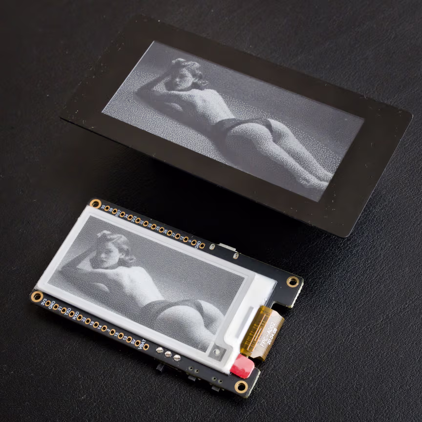
Grayscale mode
I have to include again is some rant.
What I found possibly confusing is that versioning is a mess: there are at least two versions, combining like four types of displays, two or three USB-serial converters, and different version with (another) grayscale display with a separate github repository. Specification states 212x104 or 250x122 pixels. There is even version 2.3.3 which does not have examples. Somehow I later realized that mine actually has grayscale display too! But there is not a single example how to use it. Getting theoretically working grayscale display is still better that getting something that’s advertised as grayscale but does not work.
ChatGPT strongly discouraged me from trying grayscale if it’s not documented, but I tried to modify code for my other eink display anyways. Furthermore I stumbled upon https://github.com/ZinggJM/GxEPD2_4G/blob/master/src/epd/GxEPD2_290_T94.cpp and tried their grayscale refresh waveform. Display works in grayscale (without eight pixels shift quirk), which is nice surprise. Shades of gray are different between displays and waveforms/look up tables. If you look at images above carefully, they use different dithering pattern (and crop/scale)
Summary
In the end it was quite easy. I was a bit afraid not seeing debug pins - it’s a bit scary to upload program for the first time and it proved crucial once on nRF52 due to “accident”. But maybe there are no crucial parts of boot loader on the flash, only in ROM.
I may further explore low power options, Zephyr RTOS, but I’ll keep this article focused.
At least I succeeded identifying hardware, making MicroPython work and tried grayscale mode.
Hard part was realizing how display/ssd1680 controller works (landscape, portrait), but I already did it in the past.
I still need to polish eink display code, make some wrapper for landscape mode and possibly merge it with some glyph/font drawing experiments.